
36190S.S - Control Board Installation Instructions
PDF Instructions for replacing the 36190S.S control board
Below are two sets of instructions depending on which model garage door opener you have that you are replacing the 36190S.S circuit board on. The first set is for Chan Glide Models, below that is for Chain Drive Models.
36190S CONTROL BOARD INSTALLATION INSTRUCTIONS
Replacing the control board for CHAIN GLIDE MODELS
GCG 350/350L/350ML, PCG 400/450/500ML/600/650/700ML OCG 510/550/600ML/710/750/800ML
Tools Required: 1/4” nut driver or socket, Phillips and straight blade screwdriver.
1. UNPLUG operator from 110V outlet (if the unit is permanently wired, shut off power to the unit). Open light lens and remove with motor cover (one screw) to expose control board, Fig. 1.
2. REMOVE wall control, photocell and limit switch leads (on ML models) from front terminal strip, Fig. 2.
3. REMOVE rear control board mounting bracket and 2 mounting screws at top edge of control board, Fig. 3.
4. UNPLUG wire harness and remove existing control board, Fig. 4.
NOTE: ML models do not require the following modification of the front panel as shown, Fig. 5.
5. REMOVE the three knockout covers in terminal positions 4, 5 and 6 with the straight screwdriver, Fig. 5. They must be removed to make room for the additional terminals on the new board (used only on ML models).
6. RE-CONNECT wire harness and replace with the new 36190S.S control board. Make sure board is properly seated in the front panel support details and replace the mounting bracket. Securely tighten screw. Replace mounting screws at top edge and tighten snugly (DO NOT OVER-TIGHTEN. This can cause the board to crack).
7. REPLACE motor cover and light lens.
8. RE-CONNECT wall control, photocell and limit switch leads. Do this BEFORE re-connecting main power.
9. REPLACE the motor cover. (Control boards can be light sensitive and should not be operated while uncovered.)
10. PLUG IN power cord to 110V outlet (or reset breaker).
11. ADJUST up and down force controls and program transmitter devices per the owner’s manual.
NOTE: ChainGlide models do NOT require the use of the limit switch key cap included with this kit.

36190S.S Control Board Installation Instructions
Replacement Board for CHAIN DRIVE MODELS
IC 250B, PMX 300/500 ICB, 496/696 CD/B
Tools Required: 1/4” nut driver or socket, straight blade screwdriver.
1. UNPLUG operator from 110V outlet (if the unit is permanently wired, shut off the power to the unit) and remove side cover (4 screws) to expose control board, Fig. 1.
2. REMOVE wall control and photocell leads from terminal strip, Fig. 2.
3. REMOVE control board mounting bracket at right edge of control board and 2 small mounting clips at top edge, Fig. 3.
4. UNPLUG wire harness and remove existing control board, Fig. 4.
5. INSTALL control board mounting clips and limit switch key cap on replacement board, Fig. 5.
6. REMOVE the three knockout covers in terminal positions 4, 5 and 6 with the screwdriver, Fig. 6. They must be removed to make room for the additional terminals on the new board (used only on other models).
7. RE-CONNECT wire harness and replace control board. Make sure board is properly seated in the rear panel support details and replace the mounting bracket. Securely tighten screw. Replace screws in mounting clips and tighten snugly (DO NOT OVER-TIGHTEN. This can cause the clips to crack).
8. REPLACE side cover. (Control boards can be light sensitive and should not be operated while uncovered.)
9. RE-CONNECT wall control and photocell leads. Do this BEFORE re-connecting main power.
10. PLUG IN power cord to 110V outlet (or reset breaker).
11. ADJUST up and downforce controls and program transmitter devices per the owner’s manual.

-
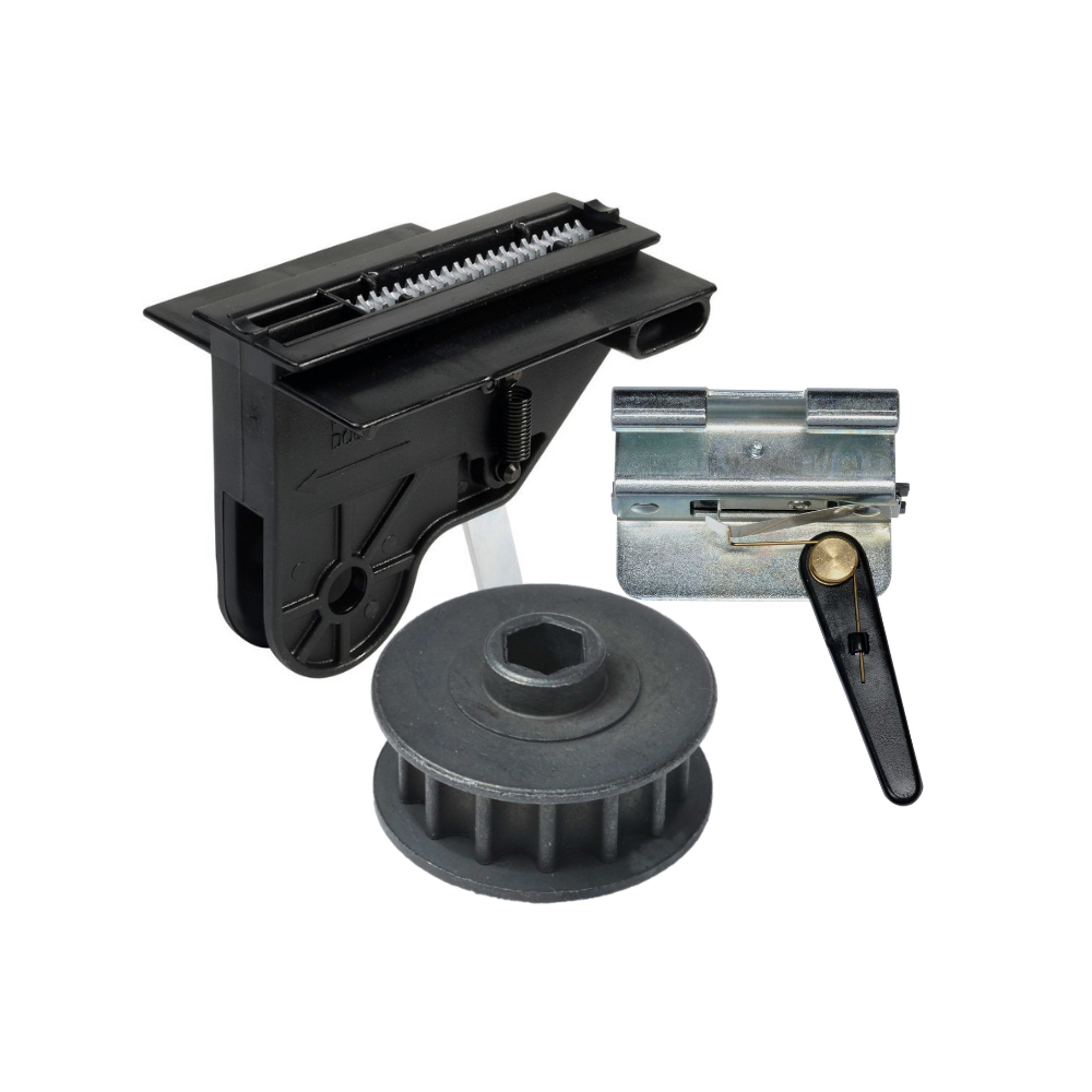
Genie Garage Door Opener Replacement Parts
Common Garage Door Problems & the Parts That Fix Them Door won’t...
-
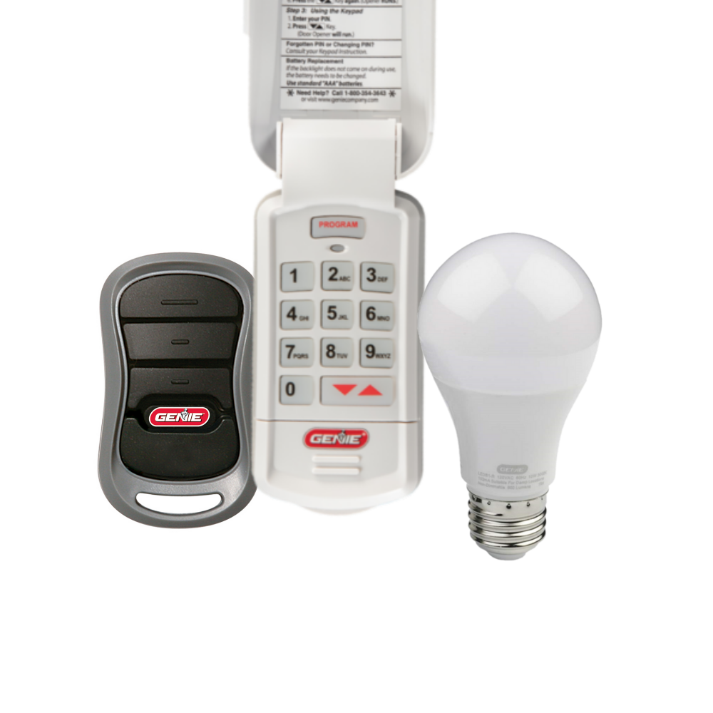
Accessories
[split] Find the right accessories for your garage door opener: The Genie...
-
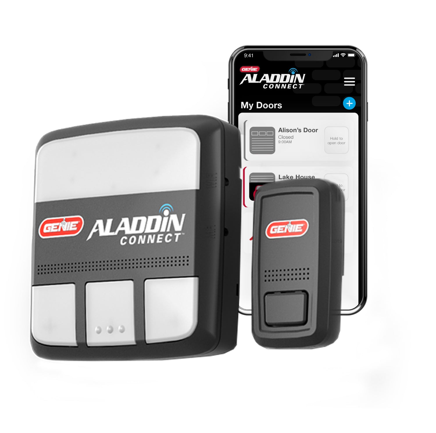
Smart Device Compatible
Smart Device Compatible Garage "Can I make my garage door opener smart?"...


