
36521S.S - Intellicode® Receiver Board Installation Instructions
PDF Instructions for replacing the 36521S.S circuit board
REPLACEMENT 36521S.S RECEIVER BOARD INSTALLATION INSTRUCTIONS
For 390 MHz Stealth/Phantom Models
WARNING
Moving door can cause serious injury or death.
• During this procedure, the Door Opener could begin to run. Stay away from moving Door and its parts. To keep Door from moving, close Door and disconnect it from Opener by pulling Emergency Release Cord.
• Keep people clear of opening while the door is moving.
• Do Not allow children to play with remote control or door opener.
• Do Not operate a door that is jammed or has a broken spring.
If the safety reverse does not work properly:
• Close door/disconnect opener by pulling Emergency Release Cord.
• Do Not use the remote control or door opener.
• Refer to Door and Door Opener Owner’s Manuals or Instructions.
WARNING
BE SURE ELECTRICAL POWER HAS BEEN DISCONNECTED FROM THE INPUT POWER LINES PRIOR TO REMOVING THE ELECTRIC BOX COVER. AN APPROPRIATE LOCKOUT/TAGOUT PROCEDURE IS RECOMMENDED. INSURE THE DOOR IS CLOSED PRIOR TO REMOVING THE OPERATOR. TEST THE DOOR FOR PROPER OPERATION AND CORRECT ANY MALFUNCTIONS PRIOR TO REINSTALLING THE OPERATOR.
Tools Required: 1/4” nut driver or socket, and/or flat blade screwdriver.
1. UNPLUG operator from 110V outlet. If the unit is permanently wired, open the circuit breaker. If you are unsure about how to shut off power to the unit, call a licensed electrician in your area. Do not reconnect power until instructed to do so.
1. UNPLUG operator from 110V outlet.
2. REMOVE the 2 screws at the top of the light cover(s), flip the cover(s) down and loosen the 2 bottom screws. Remove the cover(s)
3. ON SIDE PLATE next to the antenna wire, loosen the 2 upper side panel screws and two lower screws on the front and back plates. Remove the side plate. FIG 1

4. REMOVE and retain the receiver mounting screw. FIGURE 2
5. UNPLUG wire harness from receiver board. Note harness orientation (Green wire on left facing the connector). FIGURE 3
6. INSTALL the receiver board to bracket and carefully insert board and bracket into position. Reinstall mounting screw. FIGURE 2
7. RECONNECT wire harness to replacement receiver board. FIGURE 3


8. FEED antenna wire through a slot in the rear panel and point downward. FIGURE 4

9. REPLACE side plate.
10. PLUG the power cord into the outlet (or reset breaker).
11. ADJUST up and downforce controls and program transmitter devices following all safety and operating instructions in the owners manual.
12. REINSTALL light cover.
-
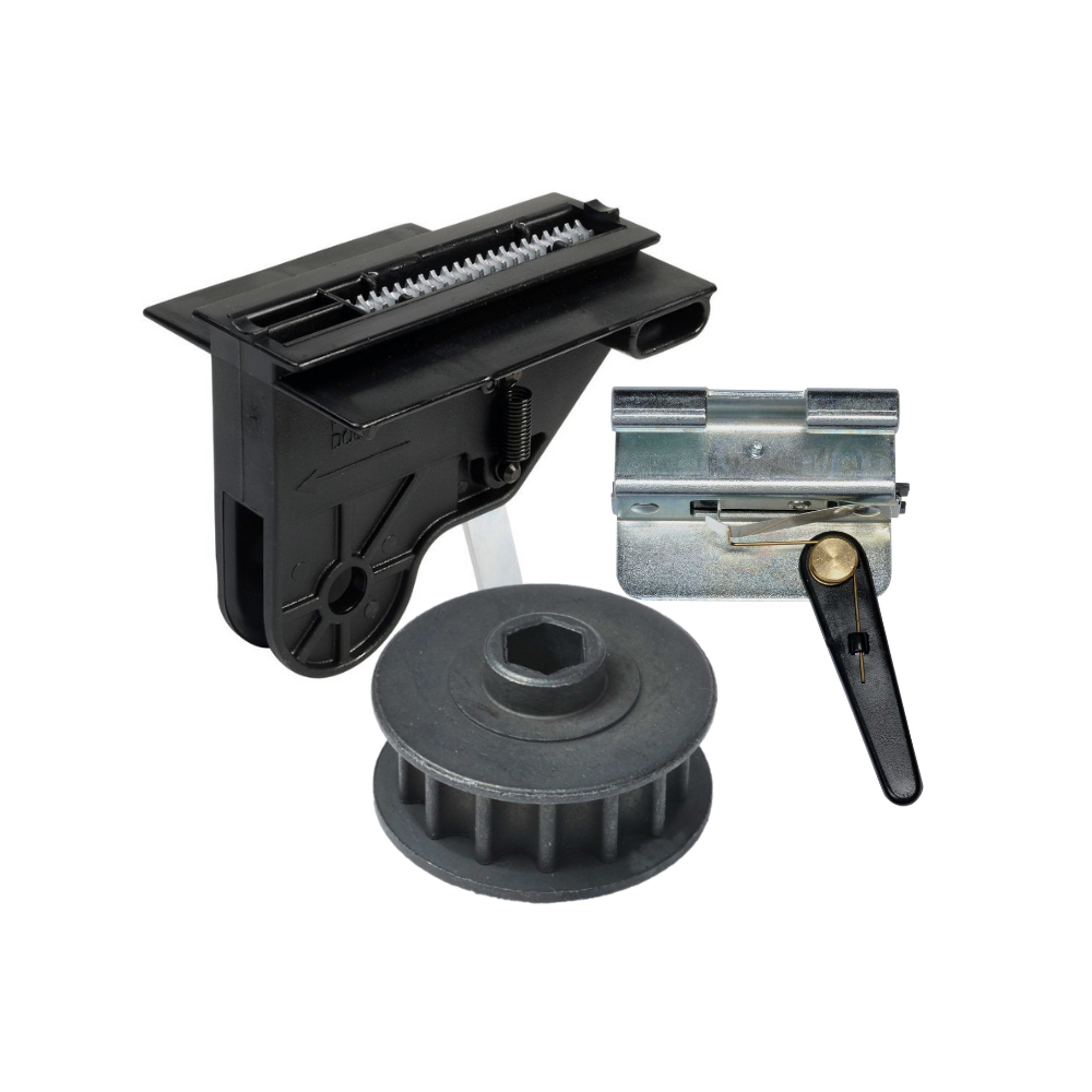
Genie Garage Door Opener Replacement Parts
Common Garage Door Problems & the Parts That Fix Them Door won’t...
-
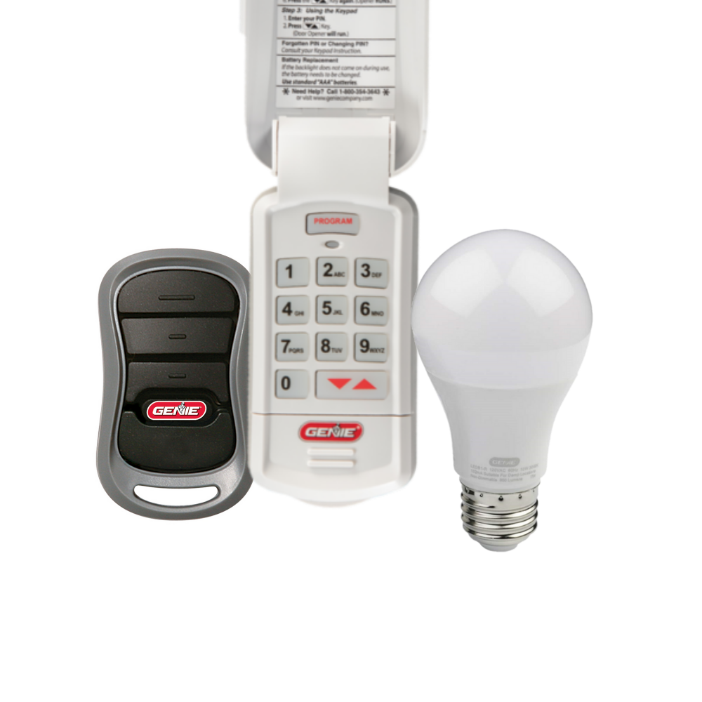
Accessories
[split] Find the right accessories for your garage door opener: The Genie...
-
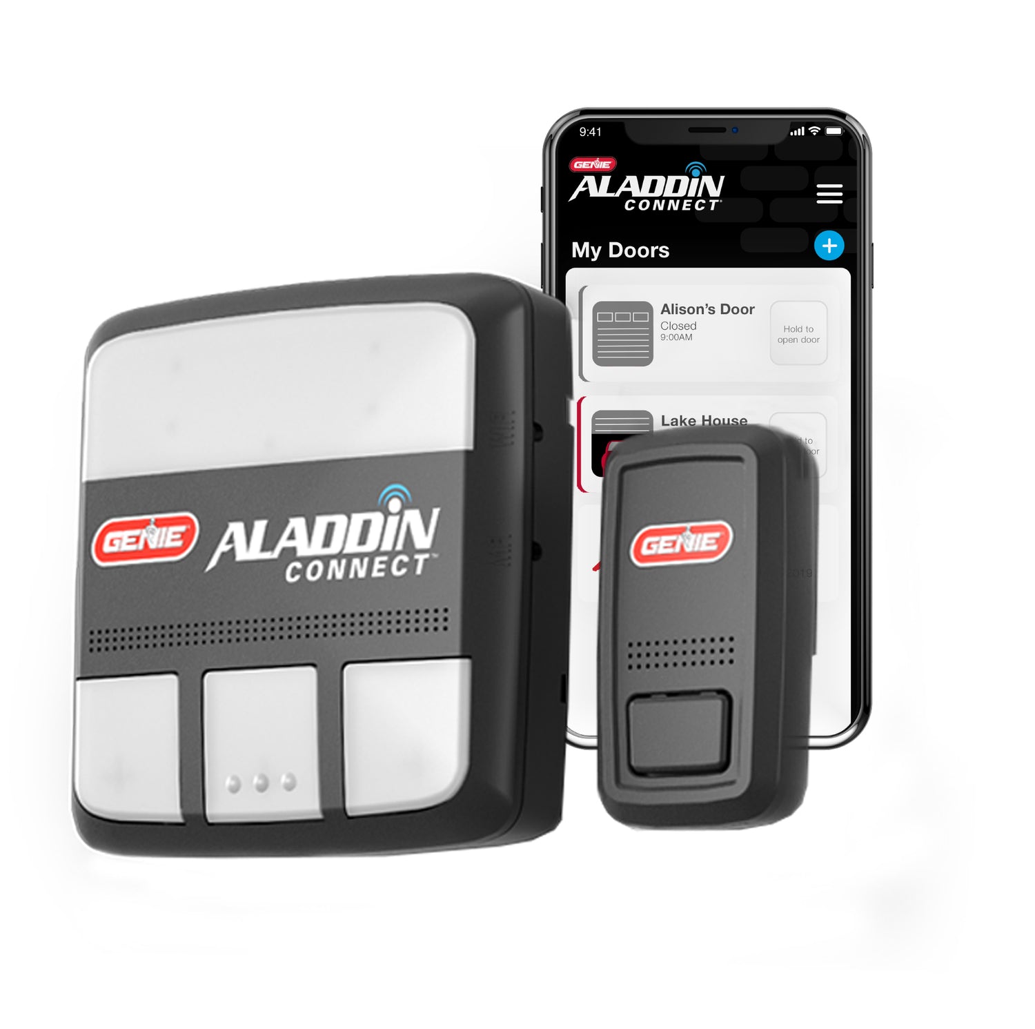
Smart Device Compatible
Smart Device Compatible Garage "Can I make my garage door opener smart?"...


