
37028E.S - Circuit Board Installation Instructions
PDF Document for Download Replacement Instructions
Replacement Control Board Assembly 37028E.S Instructions:
Tools Required: Phillips Head Screwdriver, Small Common Screwdriver
READ AND FOLLOW ALL SAFETY, INSTALLATION AND OPERATION INSTRUCTIONS AND WARNINGS CONTAINED IN THESE INSTRUCTIONS AND THE OWNERS MANUAL.
WARNING: A moving door can cause severe injury or death. When possible, use the emergency release only when the door is closed. If using the release with the door open, make sure people and objects are clear of the opening. Weak or broken springs are capable of increasing the rate and force of door closure and increasing the risk of severe injury or death.
NOTE: Do NOT remove Control Board from Cover/Button Assembly
- Pull Emergency Release Cord on Carriage to disengage opener to close the door if necessary. (If unable to lower door using opener, then use extreme caution in manually closing the door. Before pulling Emergency Release Cord, make sure people and objects are clear of door opening.)
- Remove 110 Volt power from Opener. Refer to Owners Manual for permanently wired Openers.
- Remove rear Lens/Cover. Press in on Tabs.
- Remove Wall Control and Photocell Wires from push in connections using a small screwdriver to press in on the Locking Clips. FIG 1.
- Remove two Control Board retaining screws and slide Control Board Assembly away from chassis. FIG 2.
- . Carefully remove FIVE wire connectors from old board. FIG 3.
- Install these wires onto new Control Board. The two individual RED wires may be connected to either terminal. The remaining connectors will only assemble one way. Insure that each connector is properly aligned to the Control Board Pins. FIG 3.
- Install Control Board Assembly back to Opener. Insure that all control wires are securely inside the Opener and the Antenna is extended as you slide the cover into place.
- Install two Control Board retaining screws. FIG 2.
- . Reconnect Photocell and Wall Control wires into their proper terminals. FIG 1.
- Return power to Opener. Refer to Owners Manual for permanently wired Openers.
- SET LIMITS: Please Note: These replacement circuit boards have a design change from original and will require the programmer to press and HOLD the “SET” Button for 5 seconds to set LIMITS. Additionally, the Close Limit MUST be set prior to setting the Open Limit. Refer to updated programming instructions located on the reverse side of this sheet . FIG.4.
- Reset Force Adjustments.
- Program Remote Control(s).
- Replace rear Light Lens or Cover.


CLOSE TRAVEL LIMIT
- Press and hold the "Close Travel Limit" button until the door is fully closed.
- You can quickly press and release the "Close Travel Limit" button to move the door in small increments. You can also use the "Open Travel Limit" button to move the door slightly in the UP direction.
- . Door is fully closed when the bottom edge of door presses firmly onto the ground.
- Once the door is in the desired position, press and hold the "Close SET Limit" button for 5 seconds. The LED indicator light will blink green once. This stores the closed position in memory.
OPEN TRAVEL LIMIT
- Press and hold the "Open Travel Limit" button to move the door to its fully opened position. This starts the opener moving in the UP direction.
- . Hold the "Open Travel Limit" button until the door is in the fully opened position that you desire, then release this button.
- You can quickly press and release the "Open Travel Limit" button to move the door in small increments. You can also use the "Close Travel Limit" button to move the door slightly in the DOWN direction.
- Once the door is in the desired position, press and hold the "Open SET Limit" button for 5 seconds. The LED indicator light will blink green twice. This stores the opened position in memory.

-
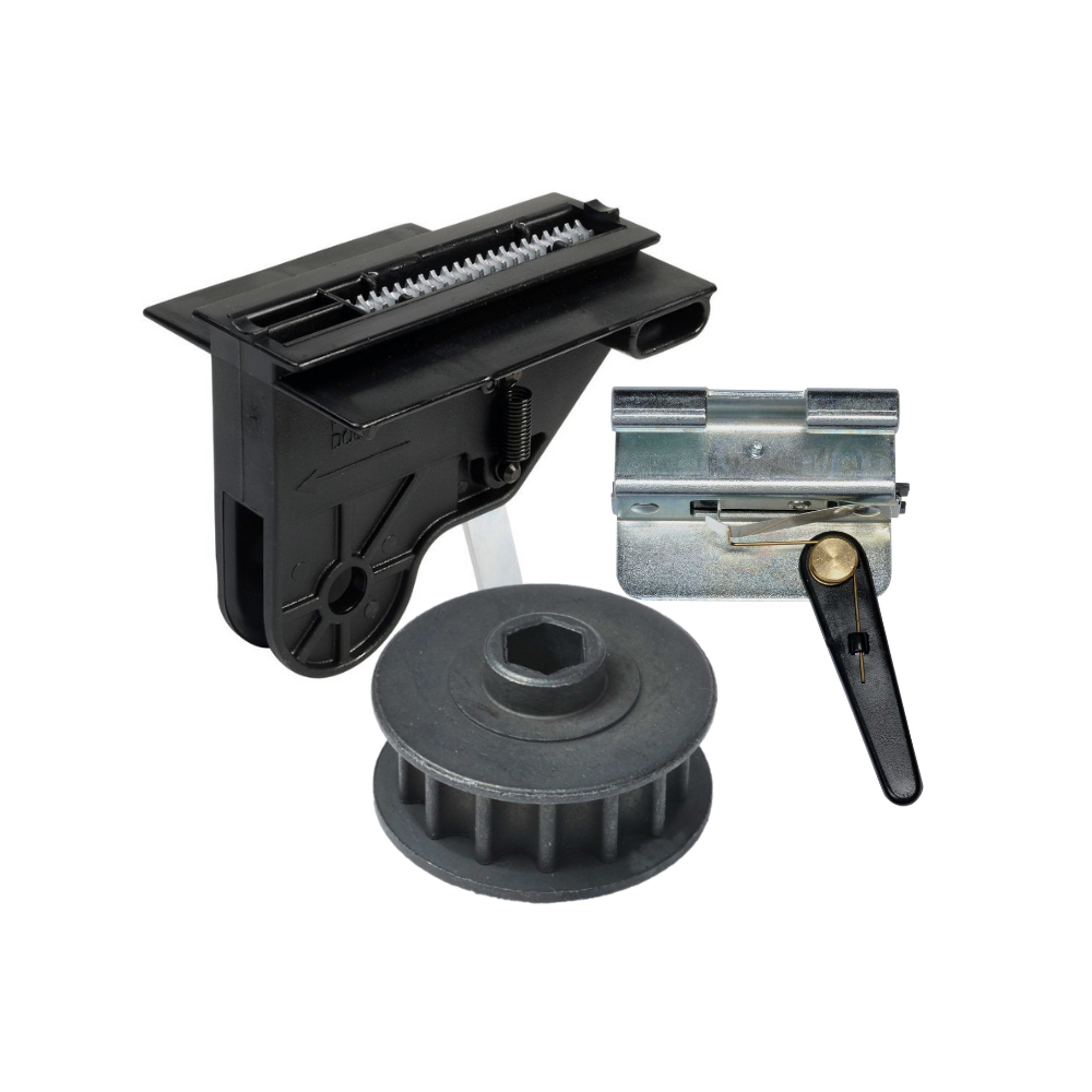
Genie Garage Door Opener Replacement Parts
Common Garage Door Problems & the Parts That Fix Them Door won’t...
-
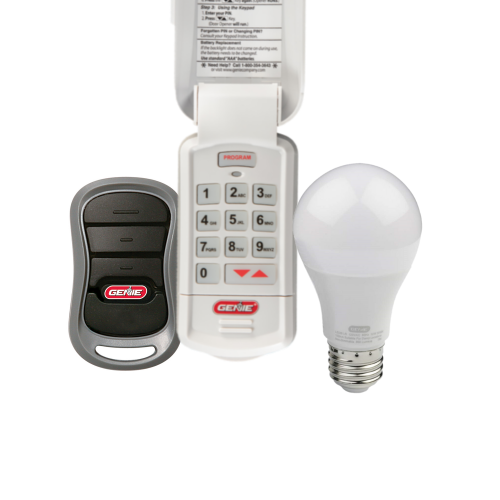
Accessories
[split] Find the right accessories for your garage door opener: The Genie...
-
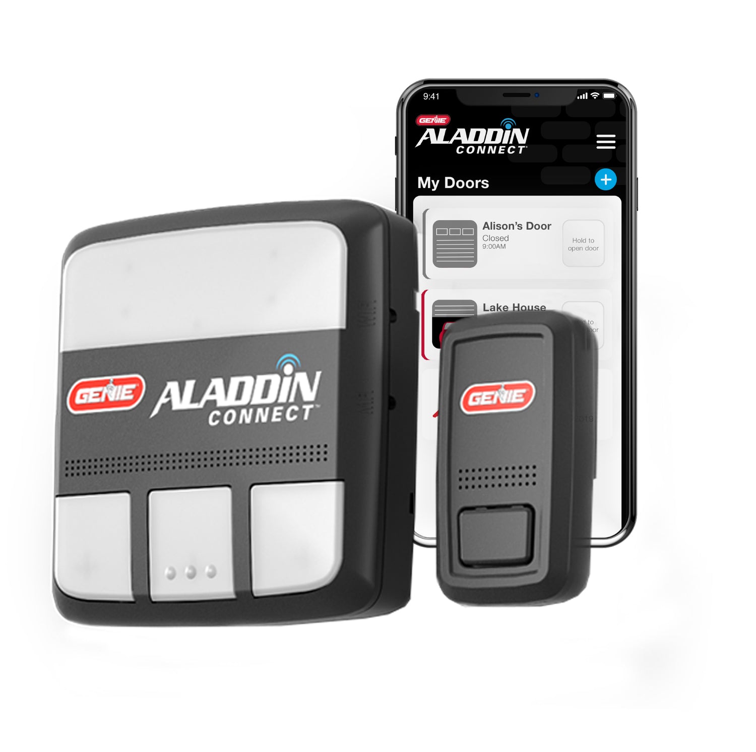
Smart Device Compatible
Smart Device Compatible Garage "Can I make my garage door opener smart?"...


