
38647R.S - Circuit Board Installation Instructions
38647R.S Control Board Replacement Instructions
WARNING
BE SURE ELECTRICAL POWER HAS BEEN DISCONNECTED FROM THE INPUT POWER LINES PRIOR TO REMOVING ANY ELECTRICAL COMPONENT COVER.
WARNING
ANY AND ALL REPAIRS MADE TO THIS UNIT MUST BE PERFORMED WITH THE DOOR DISCONNECTED FROM THE UNIT AND IN THE CLOSED POSITION.
NOTE: The garage door opener rail not shown on these images, garage door opener rail removal is not necessary for this repair.
These instructions are written assuming that you will have ample room around unit to perform this repair. Some rare instances will require removal of the unit from it’s mounting hardware and repair made on a bench or floor. Refer to your owners manual and/or installation poster for proper assembly and/or programming and carefully read and understand all warnings and cautions pertaining to your unit. Manuals/instructions can be downloaded from our websites. Refer to your unit label for website information.
Parts Included in this kit: 38647R.S Control board assembly, and two mounting screws.
Tools Required for installation: 1/4” nut driver, small common screwdriver.
Approximate Time Required for replacing the circuit board: 30 Minutes.
1. Remove power from the garage door opener (by unplugging from the outlet).
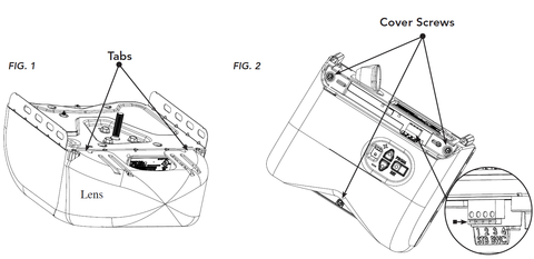
2. Press down on the tabs to remove the lens. FIG-1
3. Remove the light bulb.
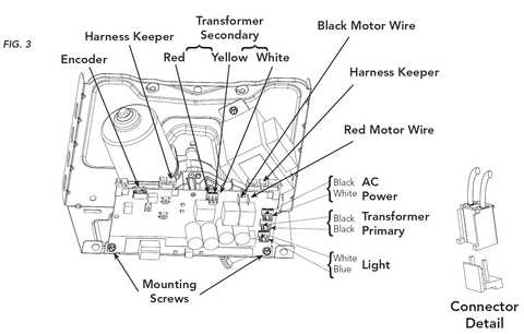
4. Note the locations and remove BWC (Basic Wall Control) and STB (Safe-T-Beam®) wires. Use a small screwdriver to press in on orange tabs to remove wires. FIG-2
5. Using a 1/4” nut driver or common screwdriver, remove the 3 opener cover screws and opener cover. FIG-2
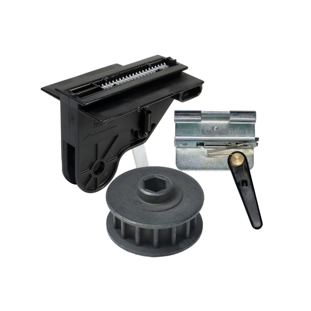
6. Note the locations and remove lights, transformer primary, AC power, red & black motor wires, transformer secondary, and encoder harnesses. FIG-3
7. Using a 1/4” nut driver or common screwdriver, remove the 2 control board mounting screws and then remove the old control board. FIG-3
8. Install the new replacement control board 38647R.S, harnesses, opener cover, BWC & STB wires, light bulb and lens in the reverse order as removed.
9. Reapply power to the garage door opener.
NOTE: Limit settings will require reprogramming. Refer to your owners manual for detailed instructions.
IMPORTANT: Test the garage door opener functions. The garage door MUST reverse on contact with a 1-1/2” high object (or a 2 x 4 board laid flat) at the center of the doorway on the floor. After adjusting either the force or limit of travel, retest door opener. Failure to adjust the opener properly may cause severe injury or death.
-
Genie Garage Door Opener Replacement Parts
Common Garage Door Problems & the Parts That Fix Them Door won’t...
-
Accessories
[split] Find the right accessories for your garage door opener: The Genie...
-
Smart Device Compatible
Smart Device Compatible Garage "Can I make my garage door opener smart?"...


