
39165R - Series II Wall Console Installation Instructions
Genie Series II Wall Console Installation Instructions

TOOLS REQUIRED

OPTIONAL TOOLS REQUIRED

OPERATION AND FEATURES.
Wall console has 3 buttons and 1 indicator backlight.
Backlight
Indicator backlight will display red when wall console is properly wired and Sure-Lock™ is OFF. When SureLock™ is ON, indicator backlight will be OFF.
Open/Close Button
This button opens and closes garage door. When Sure-Lock™ is ON, the Open/Close button will CLOSE door only.
NOTE: Constant button pressure in the CLOSE mode will override STB error responses in the powerhead and close door.
Independent Light Console Button
Use this button to turn powerhead lights ON. Powerhead lighting will remain ON until this button is pressed again or a door action has been completed.
Note: If opener has a Motion Detector, the sensor will keep the powerhead lights ON as long as motion is detected.
Sure-Lock™ Switch
When Sure-Lock™ is ON and the garage door is in the fully closed position, the powerhead cannot be activated by the wall console or a remote. Note: If Sure-Lock™ is activated while the garage door is not fully closed, the door can still be operated until the door is in the fully closed position.
• Slide the Sure-Lock™ Switch up to activate it. The backlight will be OFF.
• Slide the Switch down to turn Sure-Lock™ OFF. The backlight will be ON.

Wall Console Replacement Using Previously Installed Wiring
Need to install new wire? Wire (P/N 35265A.S), can be purchased
INSTALLING REPLACEMENT WALL CONSOLE
• Disconnect power to powerhead.
• Remove existing wall console from the wall by removing mounting screws.• Remove wires from existing wall console.
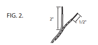
• Split and strip ends of wire if required (Fig. 2).
• Fasten wire to control board screws on back of wall console (Fig. 3):

• Connect white wire between powerhead terminal #3 to wall console terminal “W.” (Fig 3 & 7).
• Connect striped wire between powerhead terminal #4 to wall console terminal “B.” (Fig 3 & 7).
NOTE: When existing wires have a color code different from above (FIG. 3), or none at all—make sure the wires are connected between terminals as directed above. When the wires are connected to the opposite terminals, the Sure-Lock® and Light feature may not function. The first indication of incorrect wiring is the backlight will be OFF.
• Mount wall console to wall using screws provided. Verify height at least 5 ft. above floor (Fig. 4).
Reconnect power to powerhead.
• Check operation of each wall console button and feature.

Wall Console Replacement Using New Wiring
NOTE: IF MOUNTING CONSOLE IN A NEW LOCATION THAT LOCATION MUST MEET THE FOLLOWING CRITERIA:
• within sight of garage door,
• at least 5 ft. above floor (out of small children’s reach) and,
• away from all moving parts of the garage door.
DISCONNECT POWER TO POWERHEAD.
• Remove existing wall console from the wall by removing mounting screws.
• Split and strip ends of wire (Fig. 2).
• Fasten wires to control board screws on back of wall console (Fig. 3).
• Remount wall console.
• Route wire from wall console to powerhead.
• As you run wire, securely fasten wires to ceiling and wall using insulated staples (Fig. 5). Not provided. Staples should be snug only.
• Route wire through wire guide as shown in Fig. 6 to the terminals.
• Split and strip ends of wire (Fig. 2).
• Connect white wire between powerhead terminal #3 to wall console terminal “W.” (Fig 3 & 7).
• Connect striped wire between powerhead terminal #4 to wall console terminal “B.” (Fig 3 & 7).
• While pressing in locking tab, insert wire into terminal hole and then release locking tab. Confirm secure connection with a gentle tug. (Fig. 7).


NOTE: Make sure the wires are connected between terminals as directed above. When the wires are connected to the opposite terminals, the Sure-Lock® and Light feature may not function. The first indication of incorrect wiring is the backlight will be OFF.
NOTE: FOR CONNECTION TO MODELS NOT SHOWN— SEE YOUR OWNERS MANUAL.
RECONNECT POWER TO POWERHEAD.
• Check operation of each button and feature.
-
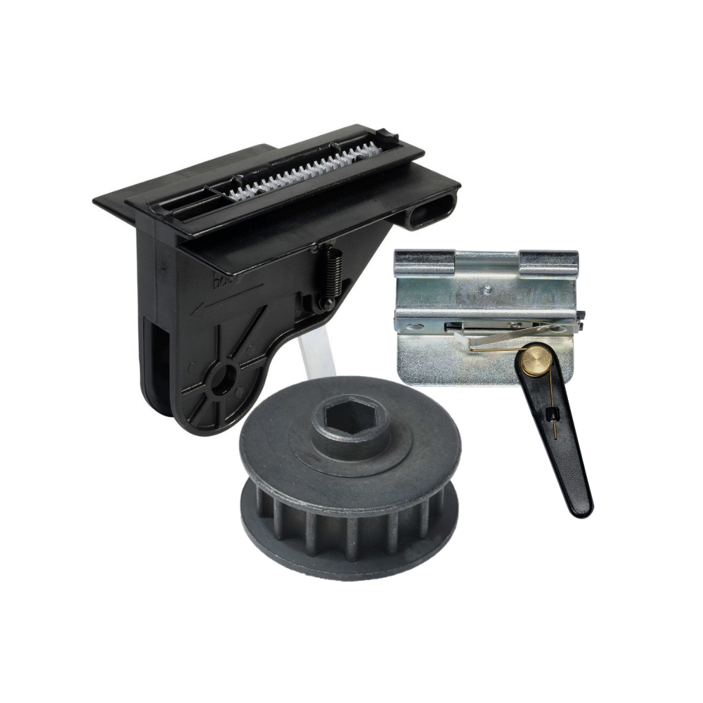
Genie Garage Door Opener Replacement Parts
Common Garage Door Problems & the Parts That Fix Them Door won’t...
-
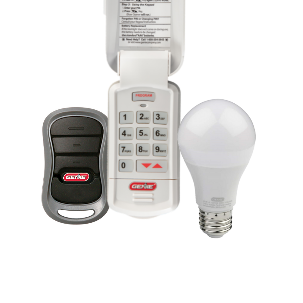
Accessories
[split] Find the right accessories for your garage door opener: The Genie...
-
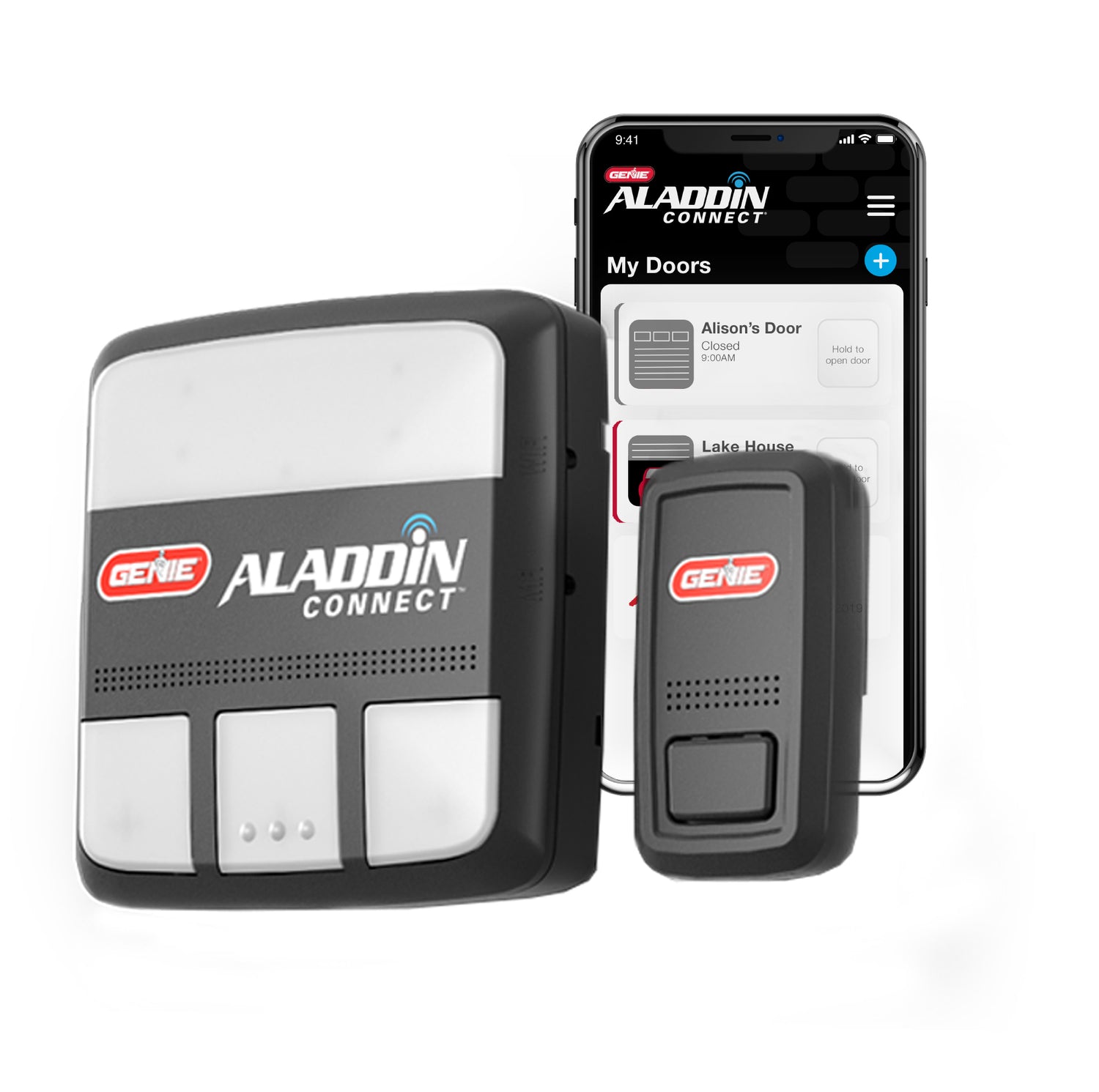
Smart Device Compatible
Smart Device Compatible Garage "Can I make my garage door opener smart?"...


