
39360R.S - Optical Encoder Installation Instructions
39360R.S DC Opto Replacement Instructions- For Belt & Chain Operators
PDF Printable instructions for replacing the 39360R.S Opto Sensor
These instructions are written assuming that you will have ample room around Opener to perform this repair. Some rare instances will require removal of the unit from it’s mounting hardware and repair made on a bench or floor. Refer to your Owners Manual or Installation Poster for proper assembly and carefully read and understand all warnings and cautions pertaining to your unit.
WARNING
BE SURE ELECTRICAL POWER HAS BEEN DISCONNECTED FROM THE OPENER PRIOR TO REMOVING THE MOTOR COVER.
WARNING
ANY AND ALL REPAIRS MADE TO THIS UNIT MUST BE PERFORMED WITH THE DOOR DISCONNECTED FROM THE OPENER AND IN THE CLOSED POSITION.
Tools required:
Standard slotted and Phillips head screwdrivers, small slotted screwdriver, 5/6” socket or nut driver.
1. Pull emergency release cord on carriage to disengage opener to close door if necessary. (If unable to lower door using opener, use extreme caution manually closing door. Before pulling emergency release cord, make certain people and objects are clear of door opening.)
2. Unplug opener power cord from power receptacle.
3. Open lens cover by pressing middle tab inward and remove light bulbs. FIG. 1.

4. Remove wall control and Safe-T-Beam wires from terminal block located on side of opener FIG. 1. Use small common screwdriver to press in on orange tabs while gently pulling wires from block. Mark wires to help facilitate replacement.
5. Unplug any optional accessories such as the battery backup and/or networking adapter.
6. Remove two 5/16” screws securing powerhead cover to chassis. FIG. 2.

7. Push cover forward slightly and allow the motor cover to swing down to access control board and wire harnesses.
8. Unplug the following harnesses from the control board. FIG. 3.
• Light harness
• Motor harness
• Opto harness
• AC IN harness
• Green ground wire to chassis (if equipped)

9. Powerhead cover can now be removed from opener chassis for repair. Special care should be taken to prevent damage to motion detector bulb located on bottom of motor cover. (If equipped).
10. Check opto harness board connector. If it matches the 6 pin harness attached to replacement opto assembly proceed to step 11. If the harness is a 4 pin type, replace harness with 4 pin type harness included with the kit. Install opto end of harness to opto plug A.
11. Remove the 2 opto cover screws from bottom of motor and discard opto assembly. FIG. 4

12. Install replacement opto assembly onto motor. If necessary, orient opto wheel slightly to align engagement lugs with motor lugs. FIG. 5. (DO NOT remove mylar cover). Opto assembly should easily fit flush with motor. Install screws.


13. Hang powerhead cover to chassis to connect all harnesses removed in step 8. Be certain to install all harnesses in the correct position being sure to install with locking tabs facing each other. FIG 3
14. Swing powerhead cover up onto chassis and secure using screws removed in step 6.
15. Install wall control and Safe-T-Beam wires. Install battery backup and/or network harnesses if applicable.
16. Install light bulbs and close lens cover.
17. Reapply power to the Genie garage door opener.
18. Limit controls may require adjustment and full function test should be performed. Refer to owners manual for detailed information. Visit our website for installation and programming instructions.
NOTE: If the garage door runs only short travel, recheck opto harness connections.
-
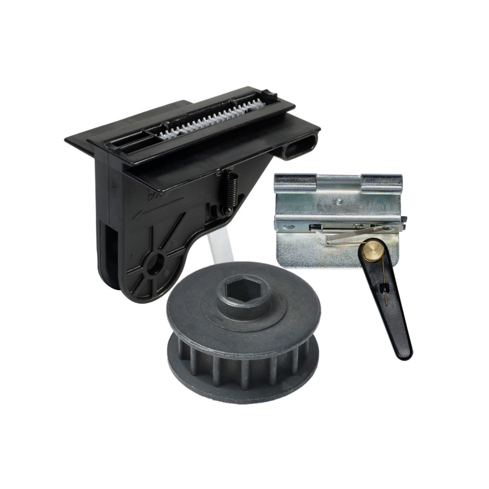
Genie Garage Door Opener Replacement Parts
Common Garage Door Problems & the Parts That Fix Them Door won’t...
-
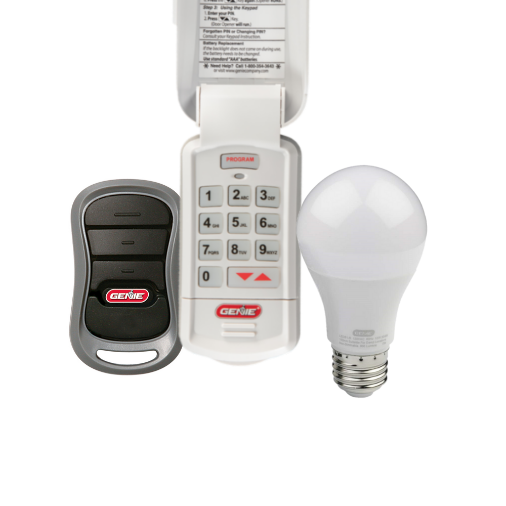
Accessories
[split] Find the right accessories for your garage door opener: The Genie...
-
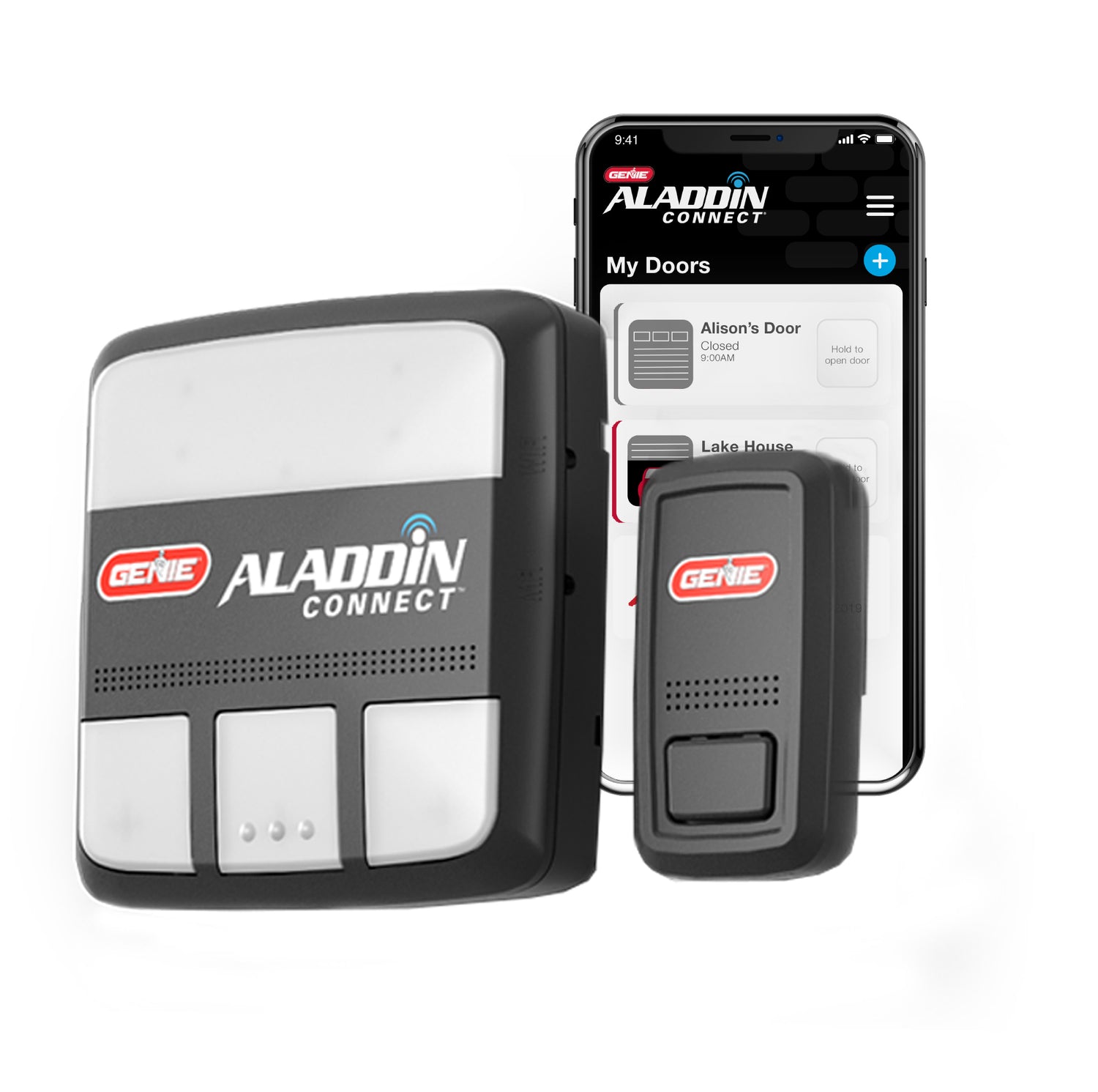
Smart Device Compatible
Smart Device Compatible Garage "Can I make my garage door opener smart?"...


