39411R.S - Replacement Belt Rail Installation Instructions
39411R.S Replacement Belt Rail Instructions
Belt Rail Replacement
For use on models: 1035, 2035, 2036, 2055, 3035, 3055, 7035, 7055 ONLY!
This repair will require removal of the unit from its mounting hardware and repair made on a bench or floor. Refer to your Owners Manual/Installation Poster for proper assembly and carefully read and understand all warnings and cautions pertaining to your unit.
WARNING
BE SURE ELECTRICAL POWER HAS BEEN DISCONNECTED FROM THE INPUT POWER LINES PRIOR TO REMOVING THE POWERHEAD.
WARNING
ANY AND ALL REPAIRS MADE TO THIS UNIT MUST BE PERFORMED WITH THE DOOR DISCONNECTED FROM THE OPENER AND IN THE CLOSED POSITION.
1. Pull emergency release cord on carriage to disengage opener to close door, if necessary. (If unable to lower door using opener, use extreme caution manually closing door. Before pulling emergency release cord, make certain people and objects are clear of door opening.)
2. Unplug the garage door opener power cord from power receptacle.
3. Remove Battery Backup (BBU) from powerhead, if equipped:
4. Unplug harness from top of the garage door opener powerhead.
5. Remove two screws securing the Battery Backup to rear of powerhead.
6. Tilt Battery Backup up and slide mounting brackets out. FIG. 1.
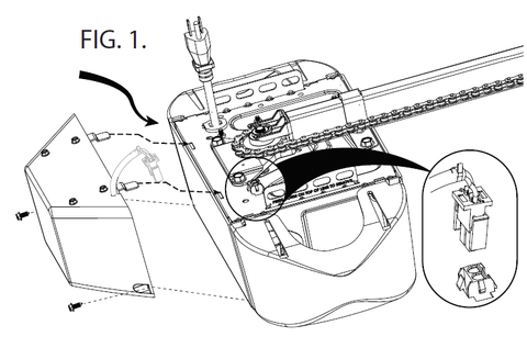
7. Set the battery backup aside.
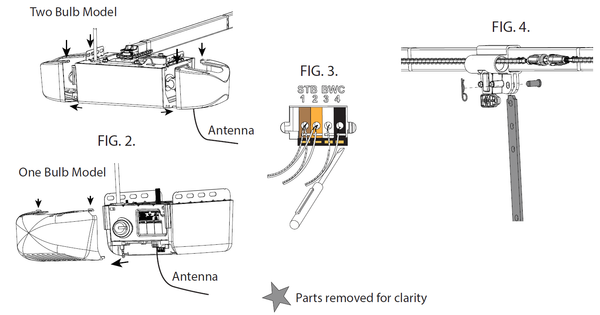
8. Remove lens cover(s) by pressing top tabs down and slide lens cover(s) out. Remove light bulbs. FIG. 2.
9. Remove wall control and Safe-T-Beam® wires from terminal block located on side of two bulb models or rear of one bulb models FIG. 3. Use small common screwdriver to press in on orange tabs while gently pulling wires from block. Mark wires to help facilitate replacement.
10. Remove clevis pin and hairpin from door arm assembly. FIG. 4.
11. Remove opener from mounting hardware and set opener assembly on clean work surface.
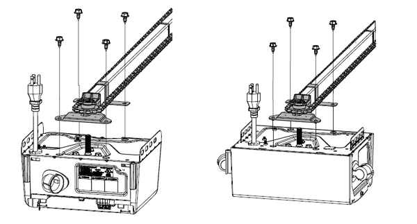
12. Remove the belt rail assembly from powerhead.
• Remove 4 bolts from rail mount on top of powerhead and slide the belt rail assembly off of motor shaft.
13. Assemble replacement rail assembly:
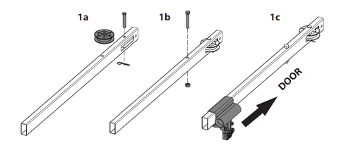
13a. Align pulley in rail slot and insert clevis pin through header rail hole and idler pulley. Secure with cotter pin.
13b. Insert 5/16”-18 x 2” bolt into header rail and secure with nut.
13c. Slide carriage assembly onto header rail section. Note “door” arrow will point towards idler pulley.
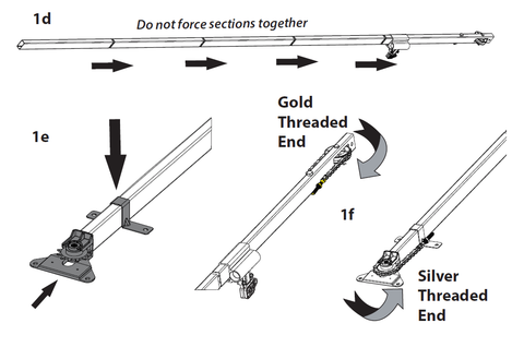
13d. Insert rail sections together by hand as shown. Assembled length is approximately 9’3”.
13e. Insert sprocket support assembly into last rail section and place rail strap onto rail.
13f. Route belt assembly gold threaded shaft around idler pulley and silver threaded end around sprocket. (NOTE: BELT TEETH SHOULD FACE RAIL)
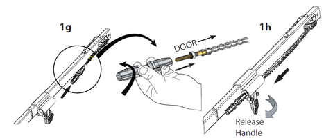
13g. Install turnbuckle with “door” end arrow onto the gold threaded end by rotating counter-clockwise one full turn.
13h. Disengage carriage assembly by rotating release handle downward and insert turnbuckle through the carriage as shown.
Ensure the belt is not twisted or bound.
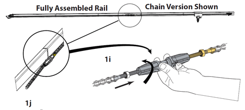
13i. Continue routing the belt assembly until turnbuckle is near the middle of the rail. Insert silver threaded shaft into
the turnbuckle and rotate turnbuckle counter-clockwise one full turn.
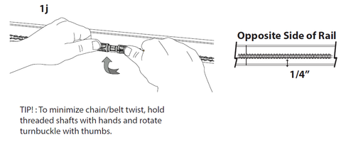
13j. Hold belt and rotate turnbuckle with thumbs counter-clockwise until the belt is tensioned properly. Measure belt tension on opposite side of rail until 1/4” from bottom of rail.
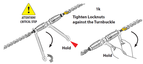
13k. Once proper tension has been established, hold turnbuckle in place with a 7/16” or adjustable wrench. Tighten both tension nuts with a 7/16” wrench.
13l. Lower the drive sprocket over the spline shaft on top of the powerhead. Align rail strap and sprocket support with holes in powerhead. Fully tighten 1/4”-14 x 5/8” self tapping screws. Do not overtighten.
13m. Install belt retainer using #6 x 3/8” self tapping screws.(Clear parts bag, Belt models only).
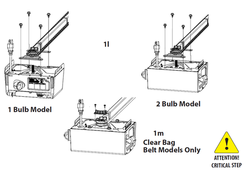
See above for installation illustrations for steps 14 -20.
14. Reinstall opener assembly to mounting hardware.
15. Reinstall door arms in reverse of step 10.
16. Install wall control and Safe-T-Beam wires.
17. Install light bulbs and lens cover(s).
18. Reengage the carriage.
19. Plug the garage door opener in.
20. Operate opener and test all safety features. Refer to your owners manual or visit www.GenieCompany.com
NOTE: Garage door opener limits may require reprogramming. Refer to your owners manual for your model.
21. Install Battery backup, if equipped. Plug the battery backup harness into the top of the garage door opener powerhead.
22. Inspect belt for sag and readjust tension if needed.
-
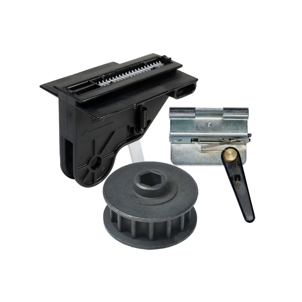
Genie Garage Door Opener Replacement Parts
Need help finding the right garage door opener part? Not sure which...
-
Accessories
[split] Find the right accessories for your garage door opener: The Genie...
-
Smart Device Compatible
Smart Device Compatible Garage "Can I make my garage door opener smart?"...


