
39732R.S - Circuit Board Installation Instructions
39732R.S Integrated Door Control Module (IDCM) Model Board Replacement
Click here for PDF (printable) 39732R.S Replacement Instructions
These instructions are written assuming that you will have ample room around Opener to perform this repair. Some rare instances will require removal of the unit from it’s mounting hardware and repair made on a bench or floor. Refer to your Owners Manual or Installation Poster for proper assembly and carefully read and understand all warnings and cautions pertaining to your unit.
WARNING
BE SURE ELECTRICAL POWER HAS BEEN DISCONNECTED FROM THE OPENER PRIOR TO REMOVING THE MOTOR COVER.
WARNING
ANY AND ALL REPAIRS MADE TO THIS UNIT MUST BE PERFORMED WITH THE DOOR DISCONNECTED FROM THE OPENER AND IN THE CLOSED POSITION.

1. Close the garage door. (If you are unable to lower door using the garage door opener, use extreme caution manually closing the garage door. Before pulling the emergency release cord, make certain all people and objects are clear of the door opening.) Pull emergency release cord on the carriage to disengage opener.
2. Unplug the garage door openers power cord from the power receptacle. or shut down the breaker.
3. Remove the Battery Backup (BBU) from the powerhead, if equipped: FIG. 1.
• Unplug the harness from top of the powerhead.
• Remove two screws securing BBU to the rear of powerhead.
• Tilt BBU up and slide mounting brackets out.
• Set BBU aside.

4. Remove lens covers by pressing top tabs down and slide lens cover(s) out. Remove light bulbs if equipped.
5. Loosen the two screws (2-A) to remove main housing cover.
6. Unplug harness (2-C) from MAIN circuit board at iDCM control board.
7. Remove two screws retaining board and remove the old board.
8. Install the new iDCM board. Carefully install iDCM mounting screw (2-B) into OPTO assembly. DO NOT overtighten.

9. Install harness (2-C) from MAIN control board to iDCM replacement board.
10. Install the main housing cover and tighten screws.
11. Install light bulbs if equipped.
12. Reapply power to the garage door opener.
13. Reprogram mobile device app to control opener with the replacement iDCM board. See special instruction included with this kit.
14. Install lens covers
15. Test all operator functions per owners manual.
16. Install BBU assembly onto motor housing if equipped.
17. Ensure that the powerhead decal has been replaced as noted above.
18. Program the APP to use the replacement board. See included programming instructions included with this kit.
-
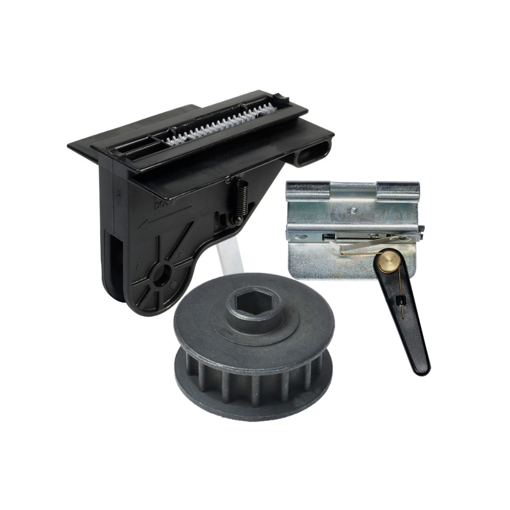
Genie Garage Door Opener Replacement Parts
Common Garage Door Problems & the Parts That Fix Them Door won’t...
-
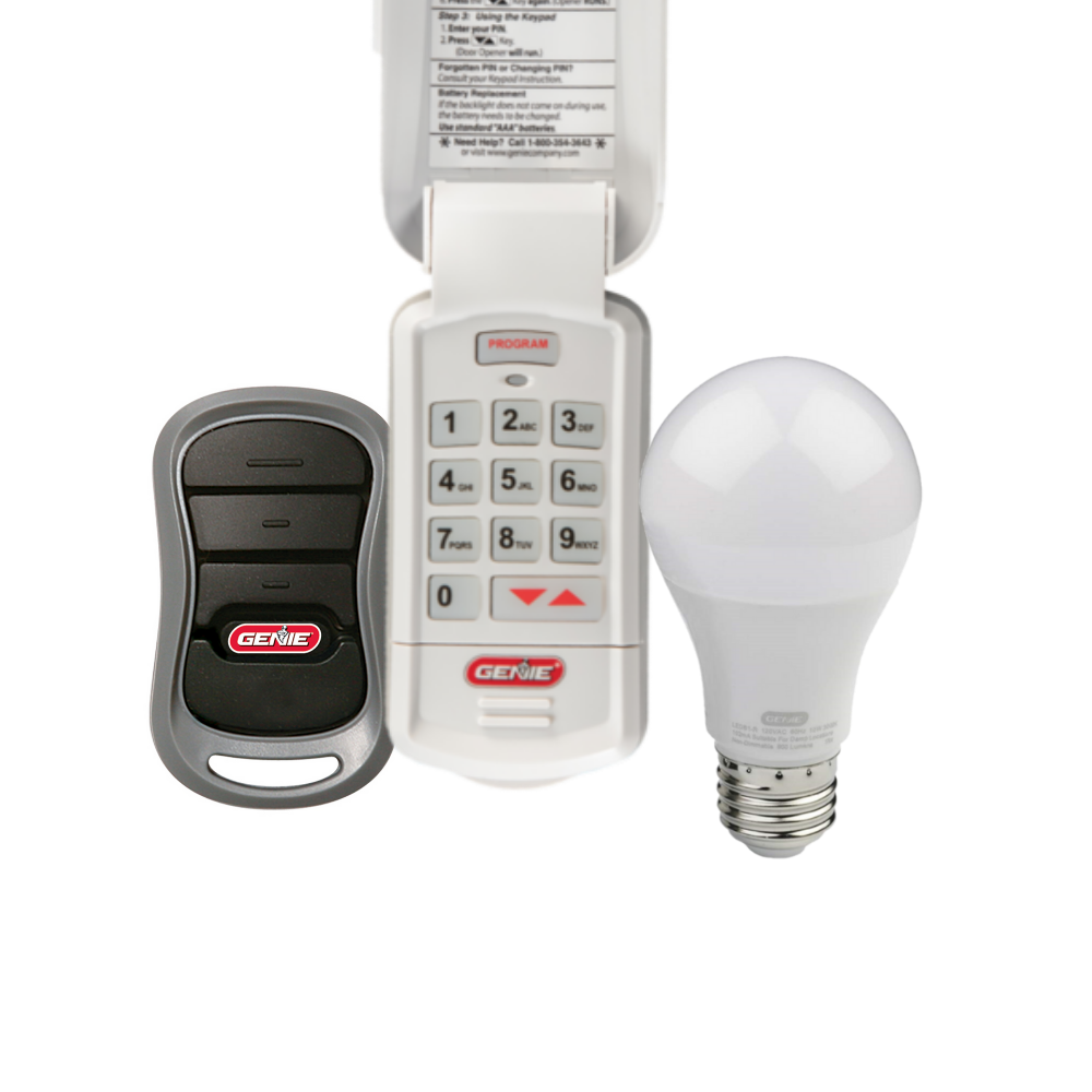
Accessories
[split] Find the right accessories for your garage door opener: The Genie...
-
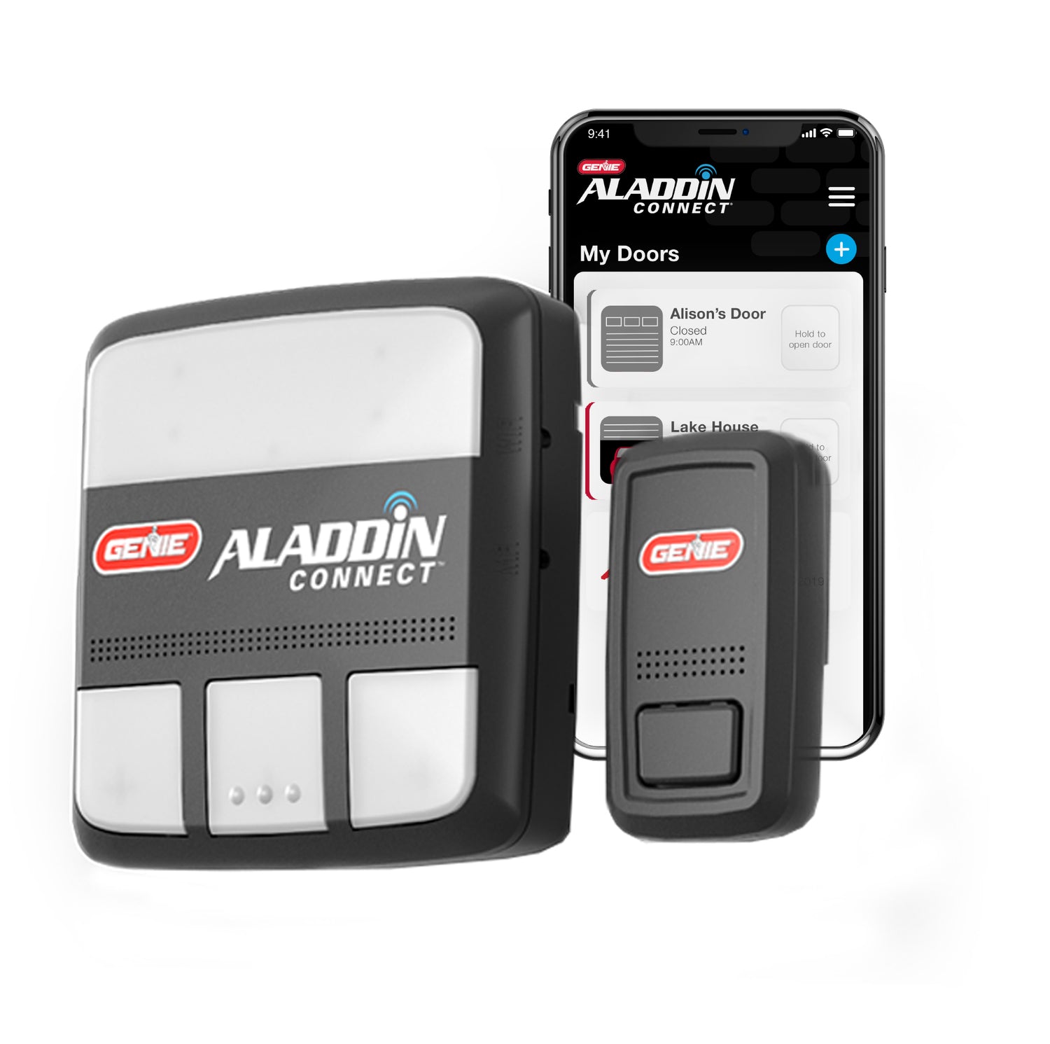
Smart Device Compatible
Smart Device Compatible Garage "Can I make my garage door opener smart?"...


