
41590R - Battery Backup for 140V Motors Installation Instructions
PDF Genie Battery Back-Up Replacement Instructions
Battery Back-Up for Residential Garage Door Openers
BATTERY BACK-UP INSTALLATION OR REPLACEMENT INSTRUCTIONS
* READ AND FOLLOW ALL SAFETY WARNINGS, CAUTIONS AND THESE ENTIRE INSTRUCTIONS PRIOR TO BEGINNING!
To Prevent possible Serious Injury or Death by Electrocution -Disconnect all electric power sources and battery power BEFORE performing ANY service or maintenance. INSTALL ONLY IN DRY LOCATIONS. NOT FOR OUTDOOR USE.
This unit to be used ONLY with Genie® Operator Models PowerMax®, SC, TriloG™, PowerLift™, SilentMax®, CB and IntelliG® that are equipped with Series II electronics. Disconnect power before performing the following tasks. Do NOT drill holes in the Battery Back-Up case.
To Reduce the Risk of Fire or Injury to Persons A. Use only the following type and size battery 12V, 8Ah (Genie® P/N 37342R). B. Do not install Battery Back-up unit on an improperly balanced door. An unbalanced door could cause severe injury or damage to this unit. Repairs and adjustments to the door must be made by trained service persons using proper tools and instructions. C. Do not dispose of the battery in fire. The cells may explode. Check with local codes for possible disposal instructions. D. Do not open or mutilate the battery. Released electrolyte is corrosive and can damage eyes or skin.TOXIC if swallowed. E. Exercise care in handling the battery to prevent shorting battery with conducting materials such as rings, bracelets & keys. F. Change the battery provided with or identified for use with this product only in accordance with the instructions and limitations specified in this instruction. G. Observe proper polarity orientation between the battery and charging circuit. H . Do not set limits while in Battery Back-up Mode. AC power MUST be connected to the opener, while setting limits, for proper operation
REQUIREMENTS This unit is designed to work with specific garage door openers on properly balanced doors with a maximum height of 8 ft. and a maximum weight of 500 lb. The unit will provide operation of the door for 24 hours after a power loss. Your garage door opener MUST have the matching Connection Cable connector in the powerhead. Do not tamper with or rewire Connection Cable. The unit may be wall mounted provided mounting location is within 24 inches of the powerhead. The unit must be inserted into the mounting bracket as far as it will go so that the bracket locks onto the ridges (Figure at Top Right) on top of the Battery Back-Up unit. This prevents the unit from moving. The unit must be mounted so that the Status LEDs are visible from the floor, and it is locked into the mounting bracket.


INSTALLATION
NOTE: DO NOT connect the Battery Back-Up Connection Cable to the garage door opener until you have completed Steps 1 & 2.
Step 1. Wire Battery
A. Remove Cover (4 screws).
— Remove foam shipping block and throw away.
B. Connect RED (+) wire to RED terminal, BLACK (–) wire to BLACK terminal.
NOTE: DO NOT REVERSE CONNECTIONS—this WILL damage the Battery Back-Up Unit.
C. Replace Cover.
Step 2. Mount
Choose mounting, Method 1 - Ceiling Mount Method 2 Angle Iron Mount and Method 3 - Horizontal Mount and attach the mounting plate using screws provided.
Method 1 - Ceiling Mount Locate and attach the mounting plate to ceiling rafter or truss using two 5/16" x 1-3/4" lag screws (provided). — Drill 3/16" pilot holes for lag screws.

Method 2 - Angle Iron Mount
A. Fasten a second perforated angle iron (not provided) to the powerhead mounting angle iron as shown using two 5/16" nuts and bolts (not provided).
B. Attach the mounting plate to the perforated angle iron using two more 5/16" nuts and bolts (not provided).

Method 3 - Horizontal Mount
A. ENSURE the locking TABS are at the bottom and attach the mounting plate with (2) two 5/16" x 1-1/2" lag screws.
B. Plug the Connection Cable into the Battery Back-Up unit.
C. Slide the Battery Back-Up unit into the mounting plate.

Step 3. Wiring to powerhead
A. Remove power from garage door opener (unplug or turn off the breaker).
B. Remove the connector port cover for the Battery Back-Up (marked "BBU") on the Powerhead
C. Plug the Connection Cable into the operator powerhead Battery Back-Up port.
D. Restore power to the garage door opener.
E. Battery Back-Up will NOT turn on until the opener has power.

Step 4. Testing
NOTE: It is recommended that the battery be allowed to charge for 24 to 48 hours prior to initial testing. Initially, the opener may not run in the Battery Back-Up mode if the battery charge is too low.
A. Run the opener using the Wall Console or Remote Transmitter to ensure it is working properly.
A. Turn off power to the garage door opener by unplugging its power cord from its grounded outlet, or turn off the breaker in the permanently installed power circuit.
B. Press the OPEN/CLOSE button on the wall control to operate the opener. It should operate the door at a lower speed.
NOTE: If the opener does not operate, recheck the connections of the Connection Cable at both the powerhead and the Battery Back-Up and try again, (SEE CAUTION BELOW.)
C. After successfully completing the test, return power to the garage door opener
REMINDER: Battery Back-Up will not turn on until power is restored to the opener
CAUTION: To remove the Connection Cable connector from the Battery Back-Up port on the powerhead, you must depress the disconnect latch before pulling the connector out of the port. Use a small screwdriver or similar device. Attempting to remove the connector without first depressing the latch will damage the circuit board

OPERATION
No user required tasks for normal use. The opener will run at a slower speed while using battery power
There are three (3) LEDs on the front housing; GREEN, YELLOW, and RED. Use the CHART.

COLOR INDICATION ACTION REQUIRED
Green LED Normal operation, No action required
Yellow LED Battery is charging, No action required
Red LED Battery voltage is below operational level. If the red LED stays on over 48 hours, the battery has failed to charge. Check Connection Cable connections and battery.
NOTE: Remember when replacing the battery—DO NOT REVERSE POLARITY [(+) and (–)] as this WILL damage the circuit board.
NOTE: To conserve battery power during a power failure (in Battery Back-Up mode), the motion detector & work light will not function.
BATTERY REPLACEMENT* SEE BELOW
A. Remove power to the opener (unplug or turn off the breaker) and unplug Connection Cable from Battery Back-Up.
B. Slide unit out of the mounting bracket.
C. Remove cover (4 screws).
D. Slide connectors off the battery.
E. Remove the old battery and insert its replacement.
F. Attach connectors, RED (+) and BLACK (–), to battery terminals.
G. Replace cover (4 screws).
H Slide unit onto the mounting bracket.
I. Plug in Connection Cable.
J . Plug in power cord.
* BE SURE YOU READ AND FOLLOW ALL SAFETY WARNINGS & CAUTIONS PRIOR TO PERFORMING THESE INSTRUCTIONS!
-
Genie Garage Door Opener Replacement Parts
Common Garage Door Problems & the Parts That Fix Them Door won’t...
-
Accessories
[split] Find the right accessories for your garage door opener: The Genie...
-
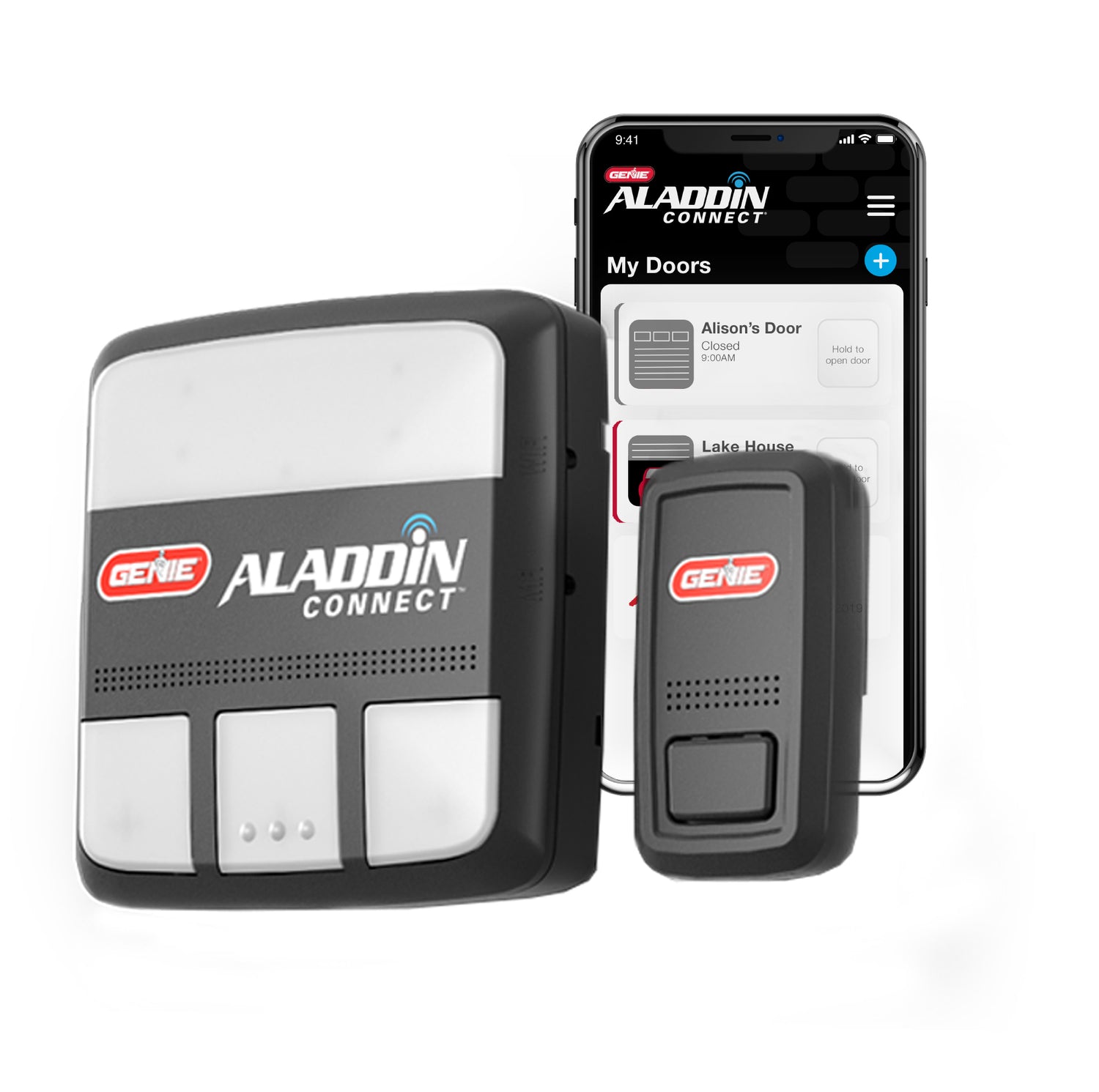
Smart Device Compatible
Smart Device Compatible Garage "Can I make my garage door opener smart?"...


