
36600R.S - Control Board Installation Instructions
PDF Installation Instructions for Replacing the 36600R.S Control Board
Controller Board (36600R.S) Replacement Instructions
1. Remove Power from Operator
2. Lower Lens Cover (figure 1)
3. Remove Light Bulbs ( figure 1)
4. Lower Cover (figure 1)
- Remove four 8-32 x 1 Phillip screws
NOTE: Leave wires connected to the terminal strip they will be removed later

5. Remove Controller Board (figure 2)
- Remove flat flex cable from Controller Board
- Remove three 8/32 screws from Controller Board
- Slide board to the right and remove
6. Install New 36600R.S Controller Board (figure 2)
- Slide board to the left being careful of the Opto Wheel and Motor Drive Board
- Align holes on Controller board with holes on the Top Plate Assembly
- Attach Controller Board with three 8/32 screws
- Attach flax flex cable from Motor Drive Board to the Controller Board

7. Install Potentiometer Shafts (figure 3)
- Push onto Potentiometer on Controller Board

8. Attach Cover to Top Plate Assembly (figure 4)
- Align holes on cover with holes on top plate assembly
- Attach with four 8-32 x 1 Phillip screws
9. Install Light Bulbs (figure 4)
- Use bulbs rated for 60 Watts maximum, rough services, appliances
- Screw bulbs clockwise into the light socket
- Close lens cover
NOTE: Do not overtighten light bulbs in sockets

10. Remove and install wires from old Controller Board terminal strip to New Controller Board Terminal Strip (figure 5)
- Remove 1 wire at a time from the old terminal strip
- Place on the new terminal strip in the same place
- Striped wire from wall control to terminal 1
- White wire from wall control to terminal 2
- white wire from STB source to terminal 2
- Striped wire from STB source to terminal 3
- One wire from "Open" limit switch to terminal 4
- One wire from "Open" limit switch to terminal 5
- One wire from "Close" limit switch to terminal 5
- One wire from "Close" limit switch to terminal 6

-
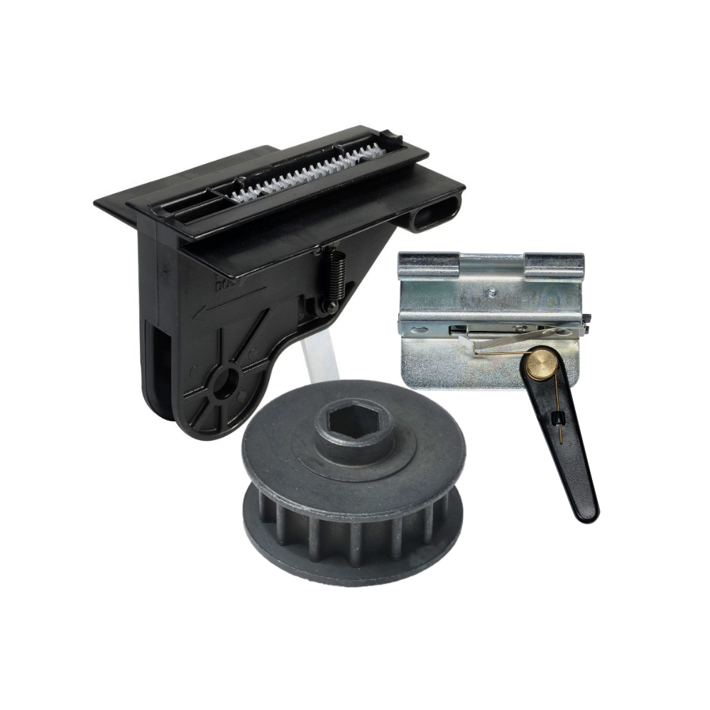
Genie Garage Door Opener Replacement Parts
Common Garage Door Problems & the Parts That Fix Them Door won’t...
-
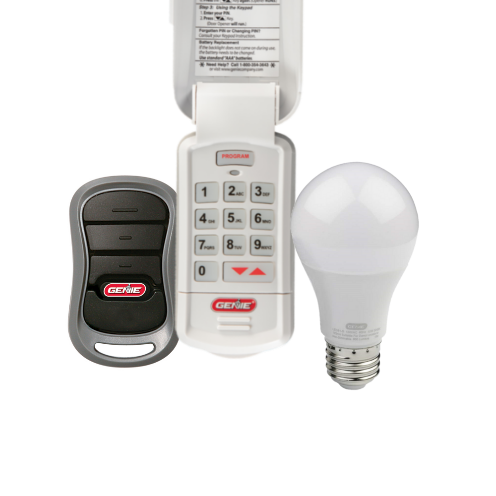
Accessories
[split] Find the right accessories for your garage door opener: The Genie...
-
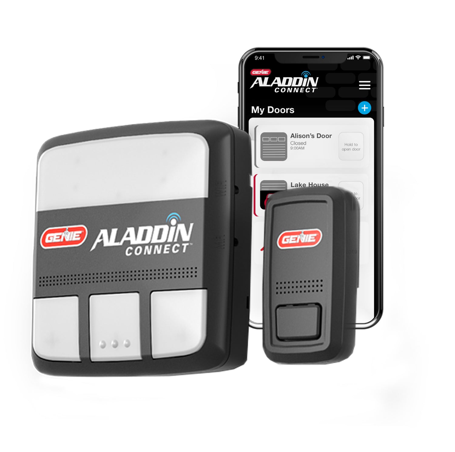
Smart Device Compatible
Smart Device Compatible Garage "Can I make my garage door opener smart?"...


