
38875R1.S - Circuit Board with Wall Console Installation Instructions
PDF Instructions for replacing the 38875R1.S Screw Drive circuit board
PDF Instructions for resetting the opener travel Limits after replacing the 38875R1.S circuit board
PDF Instructions for replacing the Genie Series II wall console
38875R1.S DC Control Board Replacement
These instructions are written assuming that you will have ample room around Opener to perform this repair. Some rare instances will require removal of the unit from its mounting hardware and repair made on a bench or floor. Refer to your Owner’s Manual for proper assembly and carefully read and understand all warnings and cautions pertaining to your unit.
WARNING!
BE SURE ELECTRICAL POWER HAS BEEN DISCONNECTED FROM THE INPUT POWER LINES PRIOR TO REMOVING THE MOTOR COVER.
WARNING!
ANY AND ALL REPAIRS MADE TO THIS UNIT MUST BE PERFORMED WITH THE DOOR DISCONNECTED FROM THE OPENER AND IN THE CLOSED POSITION.
1. Pull emergency release cord on the carriage to disengage opener to close the door if necessary. (If unable to lower door using an opener, use extreme caution manually closing the door. Before pulling the emergency release cord, make certain people and objects are clear of the door opening.)
2. Unplug the garage door opener power cord from power outlet.
3. Open the light lens cover by pressing middle tab inward and remove light bulbs. FIG. 1.

4. Remove wall control and Safe-T-Beam wires from the terminal block located on side of opener FIG. 1. Use a small common screwdriver to press in on orange tabs while gently pulling wires from the block. Mark wires to help facilitate replacement.
5. Unplug any optional accessories such as the battery backup and/or networking adapter.
6. Remove two 5/16” screws securing powerhead cover to chassis. FIG. 2.

7. Allow the motor cover to swing down to access screw drive (circuit) control board and wire harnesses.
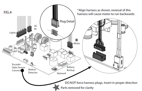
8. Unplug the following harnesses from the control board. FIG. 4.
• Light harness
• Motor harness
• Opto harness (see step 12-13)
• AC IN harness
• Motion Detector harness (if equipped)
• Green ground wire to chassis (if equipped).
REMOVE AND DISCARD.

9. Powerhead cover can now be removed from opener chassis for repair. Special care should be taken to prevent damage to the motion detector bulb (If equipped) located on the bottom of the motor cover.
10. Remove control board mounting screws and the old control board. FIG 3.
11. Feed antenna wire through the hole in the cover. Mount the 38875R1.S replacement control board to cover and secure with screws removed in step 10.
--- SEE BELOW FOR MOTOR TYPES ---
12. If your motor compares to MOTOR TYPE 1. Remove existing harness from the motor and plug pre-installed OPTO SENSOR harness from new control board directly into the motor.
13. If your motor compares to MOTOR TYPE 2. Remove pre-installed OPTO SENSOR harness from the control board and plug existing OPTO harness from the motor into DUAL ENCODER OPTO SENSOR plug on replacement control board. (Or use new harness packed with control board).
14. Hang powerhead cover to chassis to connect all other harnesses removed in step 8.
15. Swing powerhead cover-up onto chassis and secure using screws removed in step 6.
16. Install wall control and Safe-T-Beam wires. Install battery backup and/or network harnesses if applicable.
17. Install light bulbs and close lens cover.
18. Reapply power to the opener.
19. Limit controls, transmitters, and full function test will be required. Refer to the owner’s manual and/or assembly poster for detailed information
20. See below for instructions on replacing the Series II wall console

INSTALLING THE REPLACEMENT GENIE SERIES II WALL CONSOLE
• Disconnect power to the powerhead (unplug from the outlet).
• Remove existing wall console from the wall by removing mounting screws.• Remove wires from existing wall console.
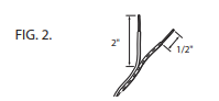
• Split and strip ends of the wire if it is needed (Fig. 2).
• Fasten the wire to control board screws on the back of the series II wall console (Fig. 3):


• Connect white wire between powerhead terminal #3 to wall console terminal “W.” (Fig 3 & 7).
• Connect striped wire between powerhead terminal #4 to wall console terminal “B.” (Fig 3 & 7).
NOTE: When existing wires have a color code different from above (FIG. 3), or none at all—make sure the wires are connected between terminals as directed above. When the wires are connected to the opposite terminals, the Sure-Lock® and Light feature may not function. The first indication of incorrect wiring is the backlight will be OFF.
• Mount wall console to wall using screws provided. Verify height at least 5 ft. above the floor (Fig. 4).
Reconnect power to the powerhead.
• Check operation of each wall console button and feature (If the circuit board was replaced, and then the wall console, reset the limits on the garage door opener before checking the wall console features.)

-
Genie Garage Door Opener Replacement Parts
Common Garage Door Problems & the Parts That Fix Them Door won’t...
-
Accessories
[split] Find the right accessories for your garage door opener: The Genie...
-
Smart Device Compatible
Smart Device Compatible Garage "Can I make my garage door opener smart?"...


