
39537R.S - Circuit Board Installation Instructions
39537R.S Circuit Board Replacement Instructions
Before replacing the circuit board on your 1022, 1024, 1042, 2022, 2024, 2042 model garage door opener, make sure to read through all the instructions.
PDF Replacement circuit board instructions
WARNING
BE SURE ELECTRICAL POWER HAS BEEN DISCONNECTED FROM THE INPUT POWER LINES PRIOR TO REMOVING THE MOTOR COVER.
WARNING
ANY AND ALL REPAIRS MADE TO THIS UNIT MUST BE PERFORMED WITH THE DOOR DISCONNECTED FROM THE OPENER AND IN THE CLOSED POSITION.
1. Close the garage door.
2. Unplug the garage door opener power cord from power receptacle or disconnect power for hardwired units.
3. Open the rear lens cover by pressing outer tabs on both sides of the motor and swing down to remove lens and light bulbs. FIG. 1.

4. Remove the wall control and Safe-T-Beam wires from the terminal block located on the rear of the garage door opener FIG. 2. Use a small common screwdriver to press in on orange tabs while gently pulling wires from the block. PRO TIP: Mark wires to help facilitate replacement.
5. Remove two screws on the rear of powerhead securing PCB board assembly to the powerhead. FIG. 3.

6. Slide PCB board assembly rearward to access internal wires and plugs.
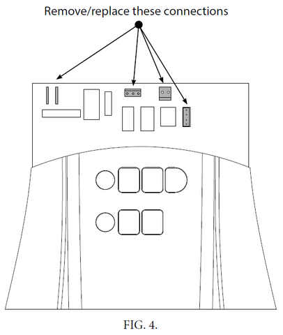
7. Disconnect motor wires, light bulb harness, opto harness, and motor harness. FIG. 4.
8. Remove PCB/cover assembly from the powerhead.
9. Remove 4 screws attaching PCB to cover and lift PCB from the cover assembly. FIG. 5. Gently pull antenna wire through the hole in the cover.

10. Gently remove force control shafts from old PCB and insert into rheostats on the new 39537R.S replacement PCB board. FIG. 6. Ensure proper placement.

11. Install the new 39537R.S replacement board onto the cover assembly in reverse order. Feed antenna wire through the hole in the cover.
12. Install motor wires, light bulb harness, opto harness, and motor harness onto PCB. FIG. 4.
13. Insert PCB/cover assembly into powerhead and install two screws to secure PCB/cover assembly.
14. Install external wall control and photocell wires into the terminal block.
15. Install a light bulb and place the lens cover back on.
16. Plug powerhead into the receptacle or apply power for hardwired units.
17. Program limits, transmitters, and force controls per owners manual.
Limit setting instructions (click here)
18. Run full operational and safety test per owners manual. See below...
-
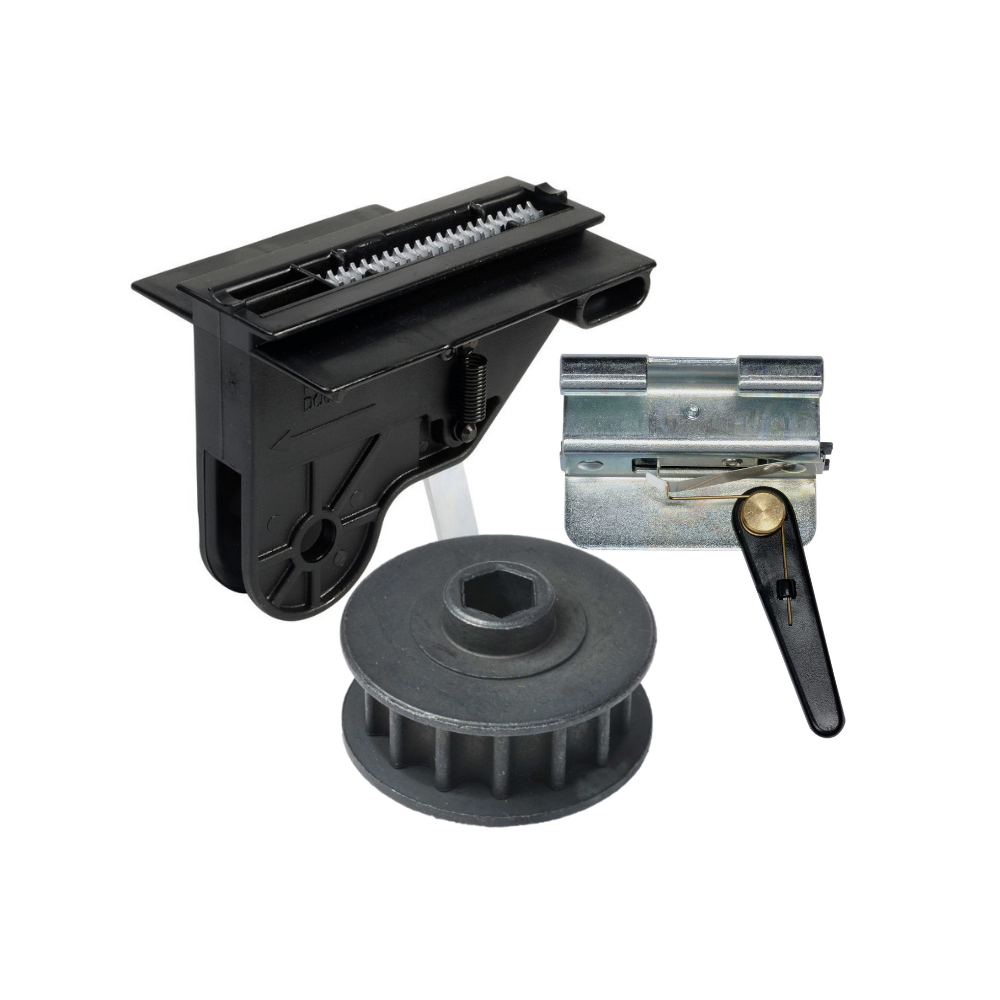
Genie Garage Door Opener Replacement Parts
Common Garage Door Problems & the Parts That Fix Them Door won’t...
-
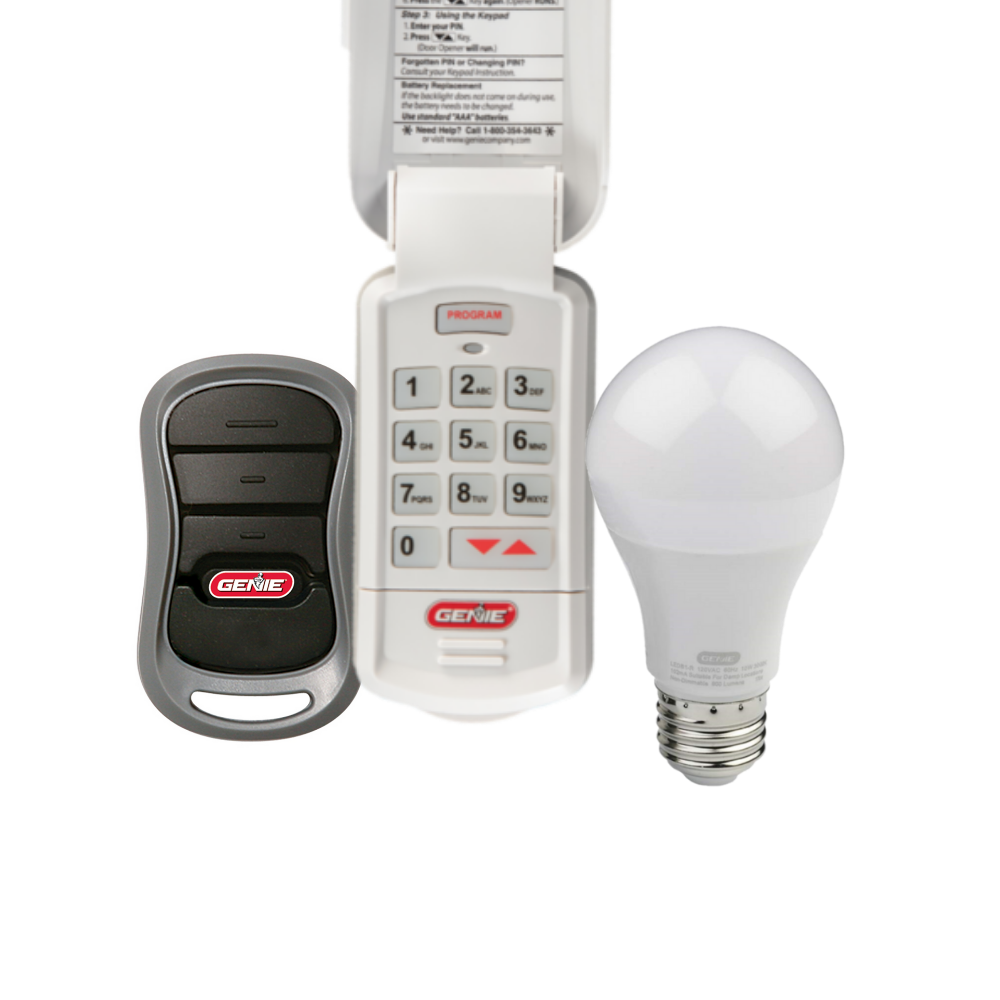
Accessories
[split] Find the right accessories for your garage door opener: The Genie...
-
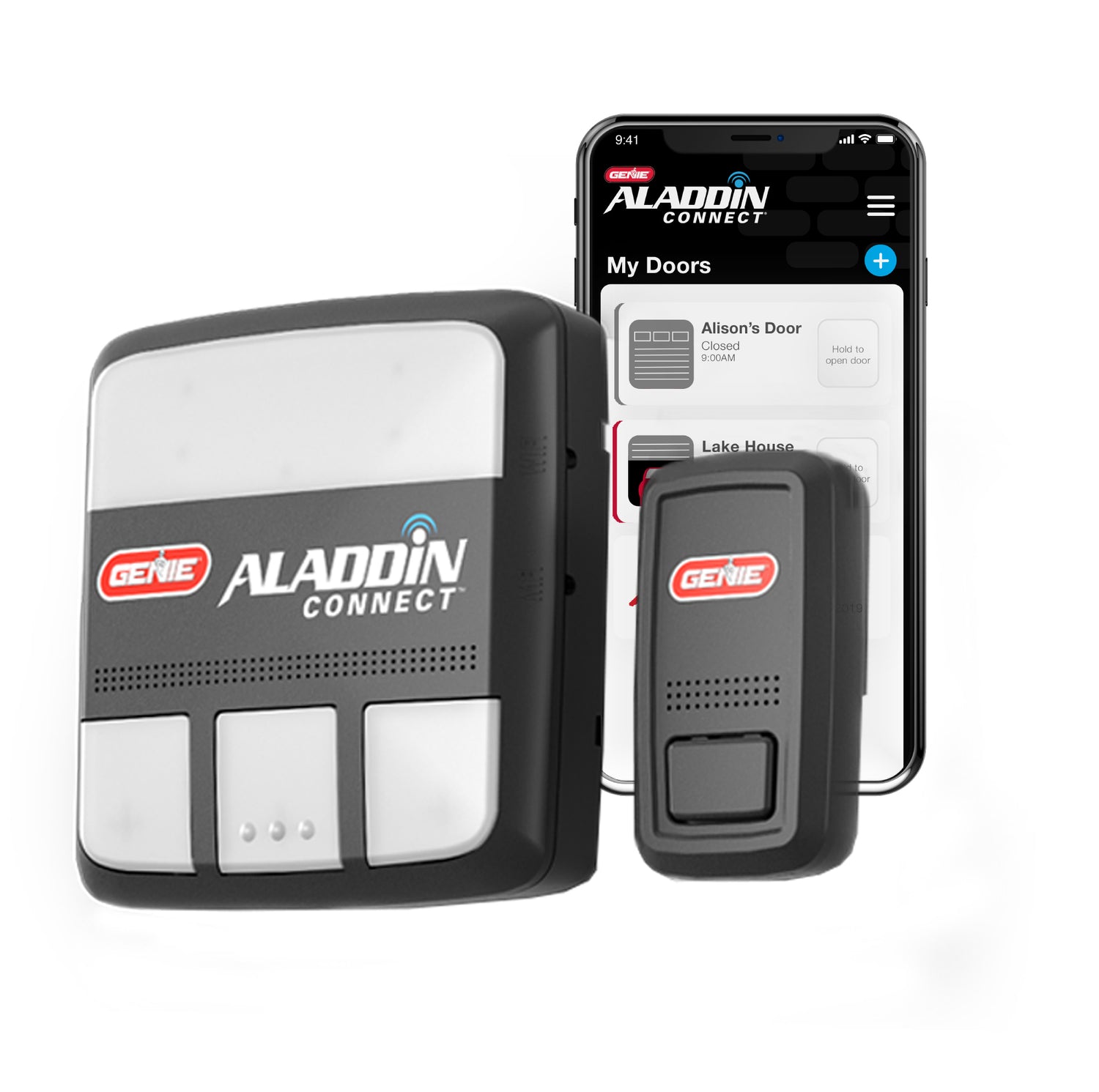
Smart Device Compatible
Smart Device Compatible Garage "Can I make my garage door opener smart?"...


