The Genie Company
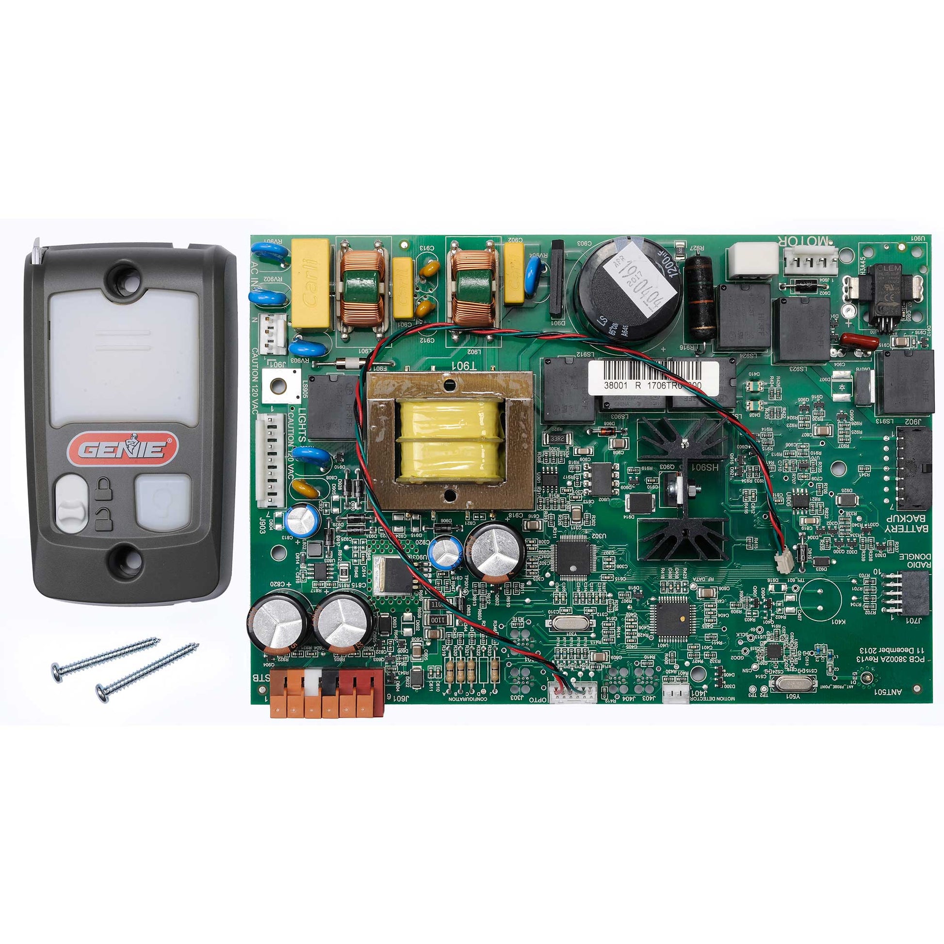
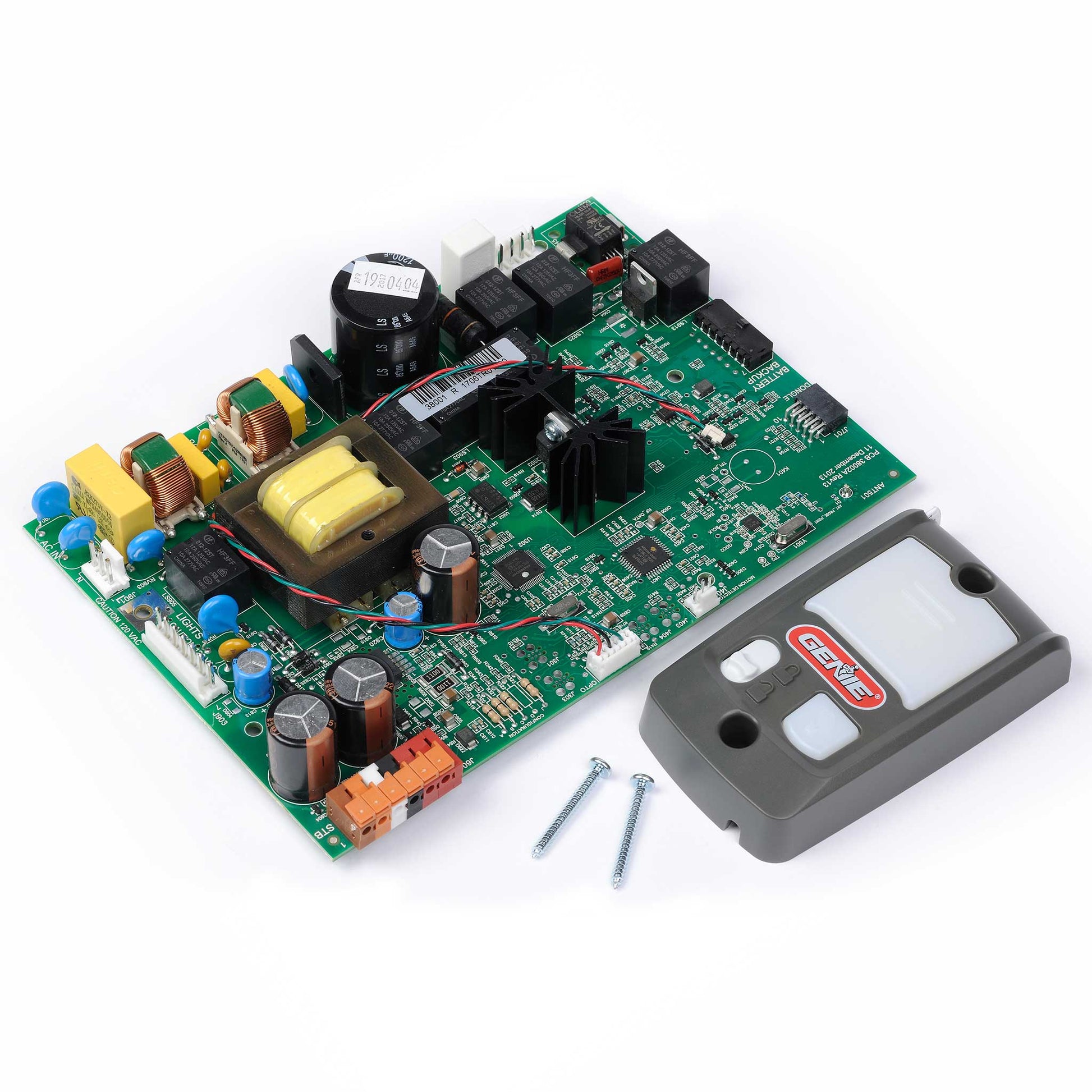
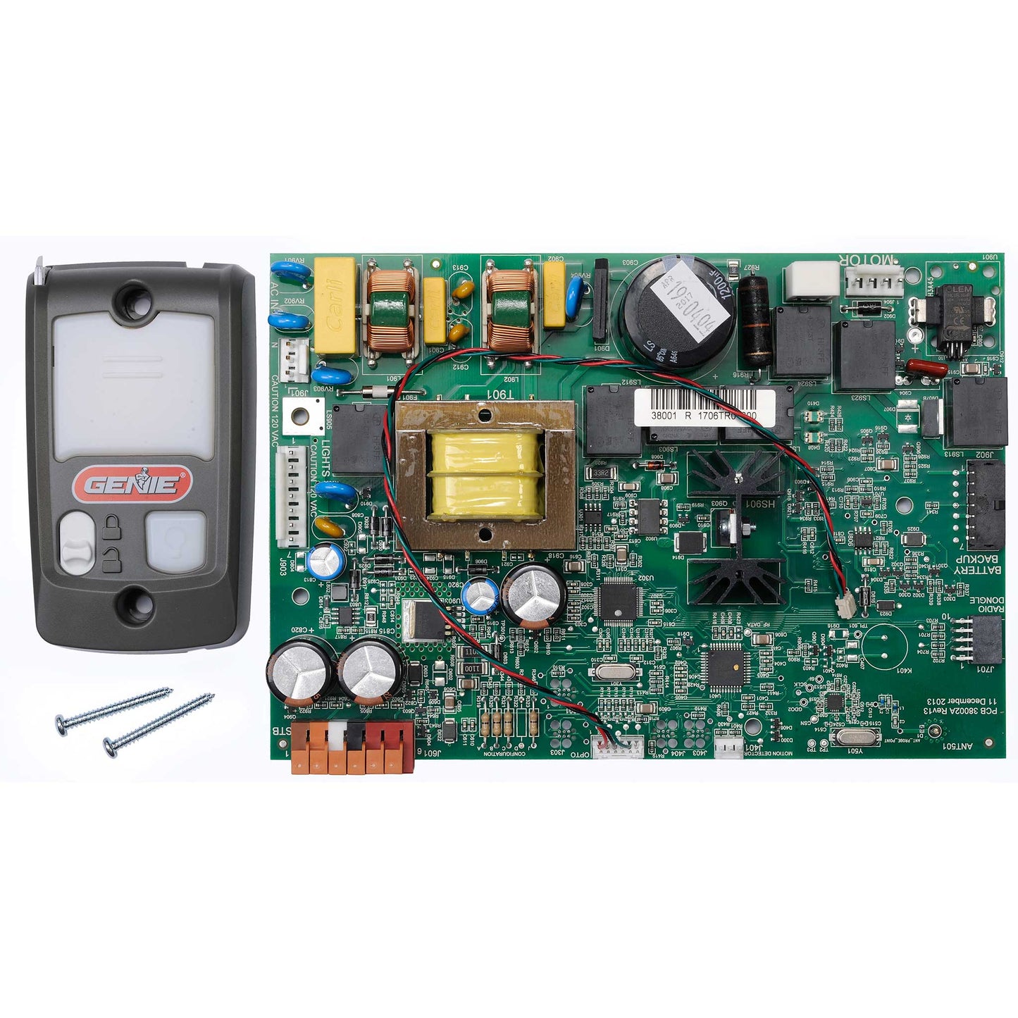
Circuit Board / Series II Wall Console Bundle 38875R4.S
Circuit Board / Series II Wall Console Bundle 38875R4.S
Couldn't load pickup availability
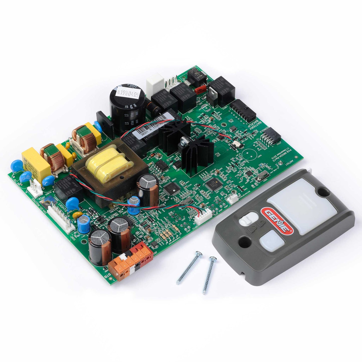
This Configured circuit board with series II wall console bundle is for Genie chain or belt drive models listed below. Use this replacement circuit board and wall console bundle to get your garage door opener back up and running quickly if you have determined your circuit board needs to be replaced.
- Compatible with models 4022, 4042, 4024 (IntelliG 1200, SilentMax 1200)
- Genuine Genie replacement parts
- Requires re-programming with the new board
- Circuit board and series II wall console included - Plus DIY detailed replacement instructions
SKU: 38875R4.S
In Stock! Usually ships within 24 hours.
ASK A QUESTION View full details
QUESTIONS & ANSWERS
Ask a Question-
Is there a switch on the board that controls the light on the wall console? Or does the unit need to be programmed? Tried switching the power wires but did not do it. Tried 3 different known good wall consoles to no avail.
There is not a switch on the board that controls that function. Please contact Genie customer service at 1-800-354-3643 for assistance.
-
What warranty comes with this replacement part?
We have a one year warranty on all purchased replacement parts and accessories.
-
will the same remote openers work?
Yes they will!
PDF Instructions for replacing the 38875R4.S circuit board
PDF Instructions for resetting the opener travel Limits after replacing the 38875R4.S circuit board
PDF Installation Instructions for replacing the Series II wall console
38875R4.S DC Control Board Replacement
These instructions are written assuming that you will have ample room around Opener to perform this repair. Some rare instances will require removal of the unit from its mounting hardware and repair made on a bench or floor. Refer to your Owner’s Manual for proper assembly and carefully read and understand all warnings and cautions pertaining to your unit.
WARNING!
BE SURE ELECTRICAL POWER HAS BEEN DISCONNECTED FROM THE INPUT POWER LINES PRIOR TO REMOVING THE MOTOR COVER.
WARNING!
ANY AND ALL REPAIRS MADE TO THIS UNIT MUST BE PERFORMED WITH THE DOOR DISCONNECTED FROM THE OPENER AND IN THE CLOSED POSITION.
1. Pull emergency release cord on the carriage to disengage opener to close the door if necessary. (If unable to lower door using an opener, use extreme caution manually closing the door. Before pulling the emergency release cord, make certain people and objects are clear of the door opening.)
2. Unplug the opener power cord from power receptacle.
3. Open lens cover by pressing middle tab inward and remove light bulbs. FIG. 1.

4. Remove wall control and Safe-T-Beam wires from the terminal block located on side of opener FIG. 1. Use a small common screwdriver to press in on orange tabs while gently pulling wires from the block. Mark wires to help facilitate replacement.
5. Unplug any optional accessories such as the battery backup and/or networking adapter.
6. Remove two 5/16” screws securing powerhead cover to chassis. FIG. 2.

7. Allow the motor cover to swing down to access control board and wire harnesses.
8. Unplug the following harnesses from the control board. FIG. 4.
• Light harness
• Motor harness
• Opto harness (see step 12-13)
• AC IN harness
• Motion Detector harness (if equipped)
• Green ground wire to chassis (if equipped).
REMOVE AND DISCARD.

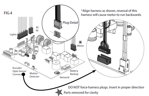
9. Powerhead cover can now be removed from opener chassis for repair. Special care should be taken to prevent damage to the motion detector bulb (If equipped) located on the bottom of the motor cover.
10. Remove control board mounting screws and the old control board. FIG 3.
11. Feed antenna wire through the hole in the cover. Mount the 38875R4.S replacement control board to cover and secure with screws removed in step 10.
--- SEE BELOW FOR MOTOR TYPES ---
12. If your motor compares to MOTOR TYPE 1. Remove existing harness from the motor and plug pre-installed OPTO SENSOR harness from new control board directly into the motor.
13. If your motor compares to MOTOR TYPE 2. Remove pre-installed OPTO SENSOR harness from the control board and plug existing OPTO harness from the motor into DUAL ENCODER OPTO SENSOR plug on replacement control board. (Or use new harness packed with control board).
14. Hang powerhead cover to chassis to connect all other harnesses removed in step 8.
15. Swing powerhead cover-up onto chassis and secure using screws removed in step 6.
16. Install wall control and Safe-T-Beam wires. Install battery backup and/or network harnesses if applicable.
17. Install light bulbs and close lens cover.
18. Reapply power to the opener.
19. Limit controls, transmitters, and full function test will be required. Refer to the owner’s manual and/or assembly poster for detailed information
20. See below to replace the wall console

INSTALLING REPLACEMENT SERIES II WALL CONSOLE
• Disconnect power to the powerhead.
• Remove existing wall console from the wall by removing mounting screws.• Remove wires from existing wall console.
• Split and strip ends of the wire if it is needed (Fig. 2).

• Fasten the wire to control board screws on the back of the wall console (Fig. 3):


• Connect white wire between powerhead terminal #3 to wall console terminal “W.” (Fig 3 & 7).
• Connect striped wire between powerhead terminal #4 to wall console terminal “B.” (Fig 3 & 7).
NOTE: When existing wires have a color code different from above (FIG. 3), or none at all—make sure the wires are connected between terminals as directed above. When the wires are connected to the opposite terminals, the Sure-Lock® and Light feature may not function. The first indication of incorrect wiring is the backlight will be OFF.
• Mount wall console to wall using screws provided. Verify height at least 5 ft. above the floor (Fig. 4).
Reconnect power to the powerhead.
• Check operation of each wall console button and feature (If the circuit board was replaced, and then the wall console, reset the limits on the garage door opener before checking the wall console features.)

-

Free Shipping
We offer FREE shipping and handling on all orders that total over $17.99 and are shipped to a US address. All orders are shipped using UPS ground, directly from The Genie Company.
-

Genuine Replacements
Buying GENUINE Genie accessories and parts guarantees that you are getting quality OEM materials backed by a Genie warranty.
-

Support
Need assistance? We are here for you! We offer a wide range of customer support options including contact by phone or email, web chat services with a live agent, and a robust support section also located on our website. All customer care teams and services are based in the USA.
