
The Genie Company
Motor Assembly (Dual Encoder) - 41014R.S
Motor Assembly (Dual Encoder) - 41014R.S
Couldn't load pickup availability
Dual encoder replacement motor assembly for the belt drive and chain drive model garage door openers listed below.Â
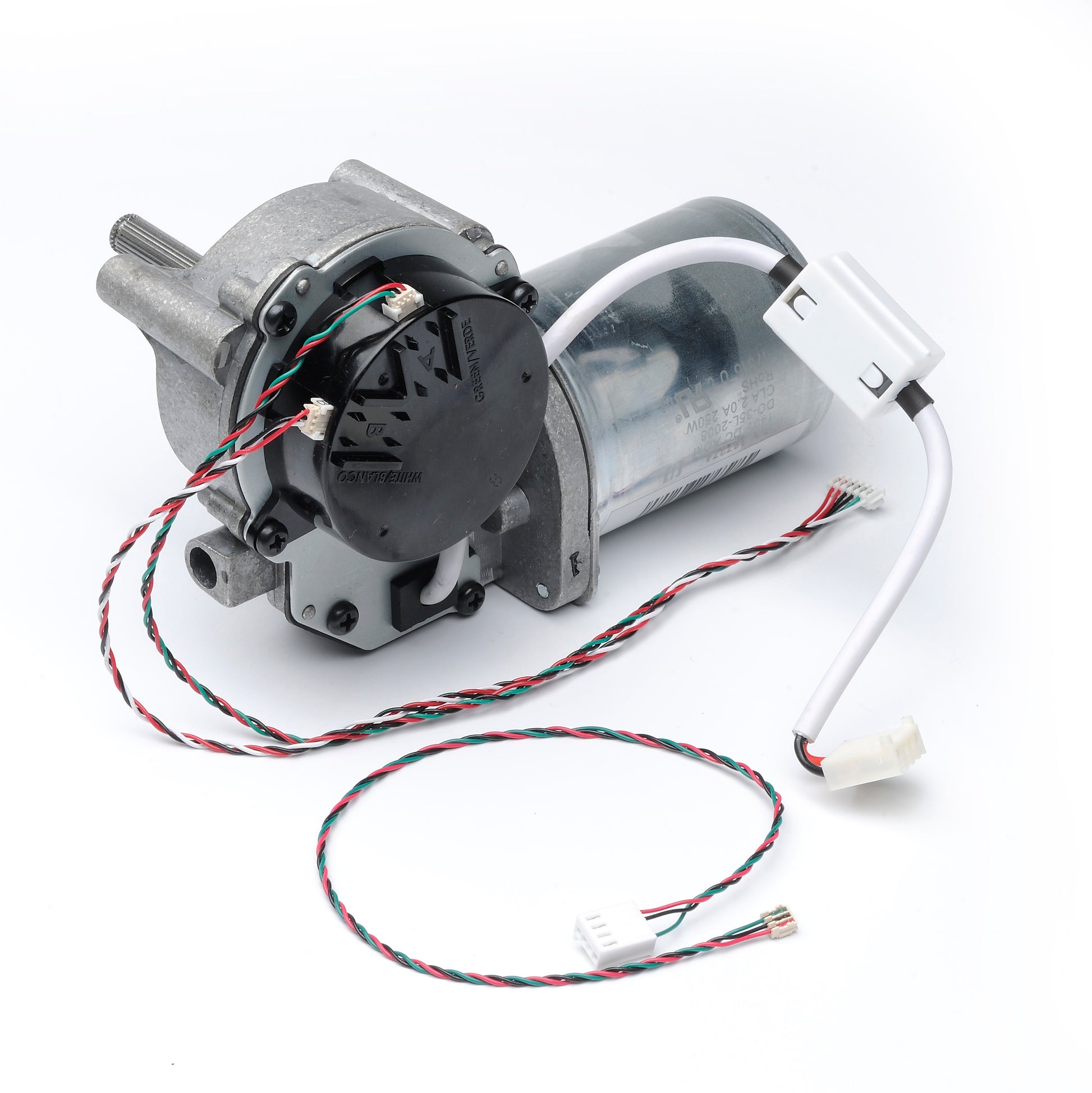
- Motor Assembly includes: Motor, Optical Encoder with cover (RPM Sensor), the wiring harness for the motor and encoder, and instruction sheetÂ
- Genuine Genie replacement partÂ
- Compatible with models:Â 3024, 4024, 3022, 3042, 4022, 4042
- Replaces 38727A.S
SKU: 41014R.S
In Stock! Usually ships within 24 hours.
ASK A QUESTION View full details

QUESTIONS & ANSWERS
Have a Question?
Be the first to ask a question about this.
Instructions for replacing the 38727A.S and 41014R.S Motor on a Genie garage door opener
PDF Printable instructions for 38727A.S Motor Replacement
38727A.S or 41014R.S MOTOR REPLACEMENT for Chain/Belt Openers
This repair will require removal of the unit from it’s mounting hardware and repairs made on a bench or floor. Refer to your Owners Manual and/or Installation Poster for proper assembly and carefully read and understand all warnings and cautions pertaining to your unit.
WARNING! BE SURE ELECTRICAL POWER HAS BEEN DISCONNECTED FROM THE INPUT POWER LINES PRIOR TO REMOVING THE MOTOR COVER.
WARNING! ANY AND ALL REPAIRS MADE TO THIS UNIT MUST BE PERFORMED WITH THE DOOR DISCONNECTED FROM THE OPENER AND IN THE CLOSED POSITION.
1. Pull Emergency Release Cord on Carriage to disengage Opener to close door if necessary. (If unable to lower door using Opener, use extreme caution manually closing door. Before pulling Emergency Release Cord, make certain people and objects are clear of door opening.)
2. Unplug Opener Power Cord from power receptacle.
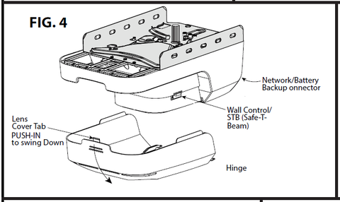
3. Open Lens Cover by pressing middle tab inward and remove Light Bulbs. FIG. 4 & 9.
4. Remove Wall Control and Safe-T-Beam wires from Terminal Block located on side of Opener FIG. 4 & 9. Use small common screwdriver to press in on orange tabs while gently pulling wires from block. Mark wires to help facilitate replacement.
5. Remove Network and Battery Backup Harnesses from front of Opener (if applicable).
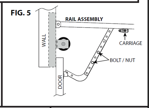
6. Remove the 2-9/16” Nuts & Bolts from Door Arms to separate door from Opener. FIG. 5.
7. Remove Motor Head and Rail Assembly from mounting brackets and set on a clean work surface or floor.
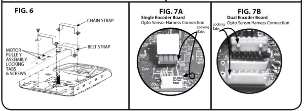
8. Remove the 4-7/16” self tapping bolts from the Rail/Motor mounting straps and pull Rail from Motor Head. FIG.6. Set Rail Assembly aside.
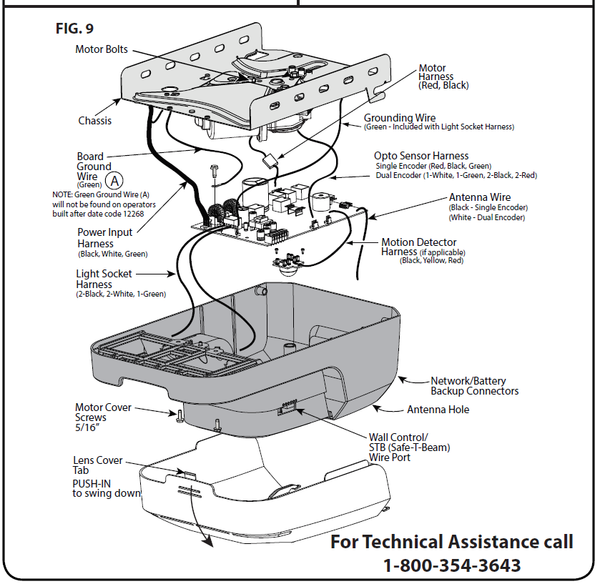
9. Remove two 5/16” screws securing Motor Cover to Chassis. FIG. 9.
10. Remove Control Board Gound Wire A (green) from Control Board if applicable. (Not required to remove from Chassis) FIG. 9.
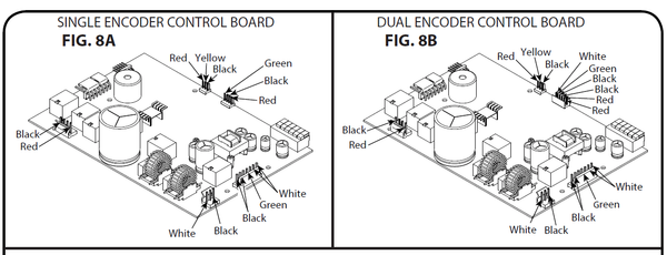
11. Unplug all Harnesses from Control Board. FIG. 8A/8B and 9.
• Light Socket Harness (2-white, 2-black, 1-green)
• Motion Detector Harness, if applicable (1-black, 1-yellow, 1-red)
• Motor Harness (1-red, 1-black)
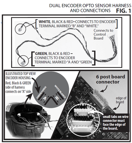
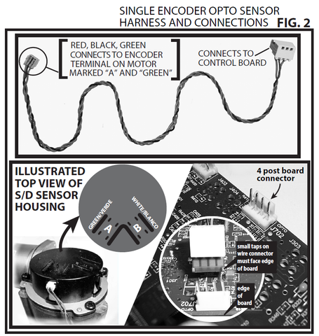
• Opto Sensor Single Encoder Harness (red, black and green wires) or Opt o Sensor Dual Encoder Harness 2 red, 2 black, one green & one white.)
• Power cord harness (Black/ White)
12. Motor Cover can now be removed from Opener Chassis for repair.
13. Remove three Motor Mounting Bolts from top of chassis FIG. 9. Remove
Motor Assembly. (Note Orientation of original Motor to aid in reassembly)
14A. Install replacement Motor Assembly in reverse order. If you have an opener
equipped with a Dual Encoder Control Board (See FIG. 8B.) Use Opto Sensor Harness attached to the Motor provided. (See FIG 1, 7B and 8B)
14B. Install replacement Motor Assembly in reverse order. If you have an opener
equipped with a Single Encoder Control Board (See FIG. 8A) use Opto Sensor
Harness from Motor Replaced or use Harness provided in kit. (See FIG. 2, 7A & 8A)
15. Install all Wire Harnesses onto Control Board. FIG. 9 and 8A/8B.
NOTE: Be certain to install all harnesses in the correct position being sure to install with locking tabs facing the proper direction.
16. Install Ground wire (A) onto Control Board (if applicable). FIG. 9.
17. Install Motor Cover onto Chassis using 2- 5/16” screws.
18. Install Wall Control and Safe-T-Beam wires. Install Battery Backup and/or Network Harnesses if applicable.
19. Install Light Bulbs and close Lens Cover.
20. Install Rail to Motor Head Assembly using the two Mounting Straps and 4-7/16” self-tapping screws.
21. Reinstall Opener Assembly in reverse order as removed. Reference
your Owners Manual and Installation Poster.
22. Plug Opener in.
23. Clear and reprogram Limit Controls per Owners Manual.
-

Free Shipping
We offer FREE shipping and handling on all orders that total over $17.99 and are shipped to a US address. All orders are shipped using UPS ground, directly from The Genie Company.
-

Genuine Replacements
Buying GENUINE Genie accessories and parts guarantees that you are getting quality OEM materials backed by a Genie warranty.
-

Support
Need assistance? We are here for you! We offer a wide range of customer support options including contact by phone or email, web chat services with a live agent, and a robust support section also located on our website. All customer care teams and services are based in the USA.


